 |
|||
|
|
|||
|
Page Title:
REMOVE DISCONNECT CLUTCH ASSEMBLY |
|
||
| ||||||||||
|
|
 TM 9-2520-270-34
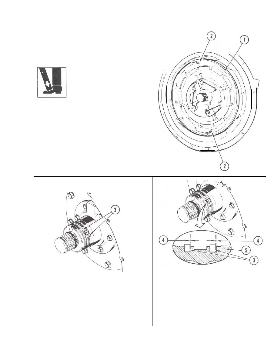
WARNING
Disconnect clutch assembly is
heavy and awkward. Remove
slowly or clutch assembly dan
fall and injure personnel.
4. REMOVE DISCONNECT CLUTCH
ASSEMBLY (1).
a. Insert two 3/8-24 X 2-3/4-inch long
hex head screws (backup plate mount-
ing screws) (2) in opposite screw
holes.
b. Using two screws (2) as handles,
pull out clutch assembly (1).
c. Remove two screws (2) used for
removal of clutch assembly.
6. CHECK SEALS (3).
a. Using feeler gage, measure gap (4)
between seals (3) and body hub (5).
5. INSPECT SHAFT SEALS (3).
b. If gap (4) is more than .OlO inch
a. Inspect seals (3) for damage.
mm), go to step 7. If not, go to
See page 2-5.
step 8.
b. If seals (3) are not damaged, go to
7. REPLACE INPUT BEVEL ASSEMBLY
step 6. If seals are damaged, go to
SHAFT SEALS. See page 4-122.
step 7.
GO TO NEXT PAGE
4-79
|
|
Privacy Statement - Press Release - Copyright Information. - Contact Us |
