 |
|||
|
|
|||
|
|
|||
| ||||||||||
|
|
 TM 9-2520-270-34
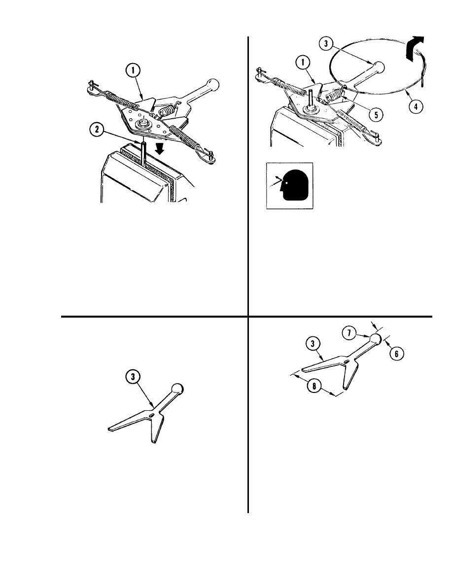
WARNING
Do not allow steering arm
t o come off punch when
disconnecting ball arm
spring. Personnel can be
injured.
3 . DISCONNECT BALL ARM (3).
a.
Thread Iockwire (4) through hook of
ball arm helical spring (5) and
form into loop.
2. PLACE STEERING ARM ASSEMBLY (1)
ON PUNCH (2).
b.
Pull Iockwire (4) up and out to release
hook of spring (5) from ball arm (3).
a. Secure 1/8-inch punch (2) in vise.
c.
Slide ball arm (3) out of steering
b. Place steering arm assembly (1) on
arm assembly (1).
punch (2).
5. CHECK BALL ARM (3).
a.
Using micrometer caliper set, measure
diameter (6) of ball (7).
Replace ball arm (3) if measurement
b.
is less than 0,4997 inch (12.692 mm).
Using indicator caliper, measure
c.
distance (8) across y-part of ball
4.
INSPECT BALL ARM (3) FOR WELD
arm (3).
CRACKS, SURFACE DAMAGE, OR
BENDS.
Replace ball arm (3) if measurement is
d.
less than 2.398 inches (60.91 mm).
a. Replace ball arm (3) if damaged.
GO TO NEXT PAGE
3-47
|
|
Privacy Statement - Press Release - Copyright Information. - Contact Us |
