 |
|||
|
|
|||
|
|
|||
| ||||||||||
|
|
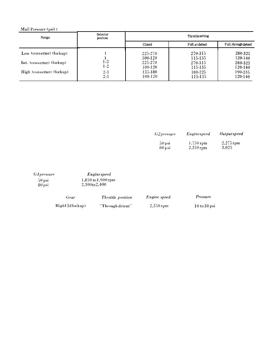 Hydraulic
Pressure
Chart
Rear Governor (G2) Pressure:
NOTE
Rear governor pressure is measured during
Lockup pressures should be measured at
operation in high range (third gear) lockup when
1,900 to 2,000 rpm engine speed. Use the
-
the engine speed is measured. It may be measured
vehicle service brakes, if necessary, while
during converter operation if transmission output
measuring full throttle "at detent" or
speed is measured.
"through detent" pressures. converter
pressures for low range (first gear) and
intermediate range ( s e c o n d gear) "at
detent" or "through detent" should be
measured while the transmission output is
rpm
stalled.
Front Governor (Gl) Pressure:
Lubrication Pressure:
Front governor pressure is measured during
Transmission lubrication pressure is checked
lockup while operating in selector position 1.
at the cooler return line.
rpm
NOTE
(1) With manual selector control at neutral
Do not attempt to connect or disconnect
(N), start engine and run it until transmission
pressure gages while engine is operating.
temperature reaches normal (180 to 200 F.).
Shift through all gears to fully charge hydraulic
(1) There are four pressure check points on
the transmission (fig. 5-142). Three are on the
system with oil.
lower-left side of the transmission housing. The
NOTE
remaining one is at the lower-rear of the housing.
It may be necessary to shift to high-range
These points have plugs which are removed to
position and operate transmission at 1,200
attach pressure gages as follows:
to 1,500 rpm (1,000 rpm engine speed)
Lockup pressure check point
while applying vehicle brakes (or locking
( 1/8 NPTF)--0-400 psi gage from kit
transmission output) to reach norm a 1
4910-572-8612.
operation temperature.
Main pressure check point
CAUTION
( NPTFT)--0-400 psi gage from kit
Do not allow converter-out (cooler) oil
4910-572-8612.
temperature to exceed 300 F.
Front governor (Gl) pressure check point
(2) Check transmission and external oil lines
( NPTF)--0-100 psi gage from kit
for leakage.
4910-572-8612.
(3) Before any oil pressure tests are made,
Rear governor (G2) pressure check point
check engine idling speed. Engine idling speed is
( 1/8 NPTF)--0-100 psi gage from kit
500 to 600 rpm. Refer to note following (1) above.
4910-572-8612.
b. Oil Pressure.
|
|
Privacy Statement - Press Release - Copyright Information. - Contact Us |
