 |
|||
|
|
|||
|
Page Title:
Figure 5-137. Converter stack-control dimension |
|
||
| ||||||||||
|
|
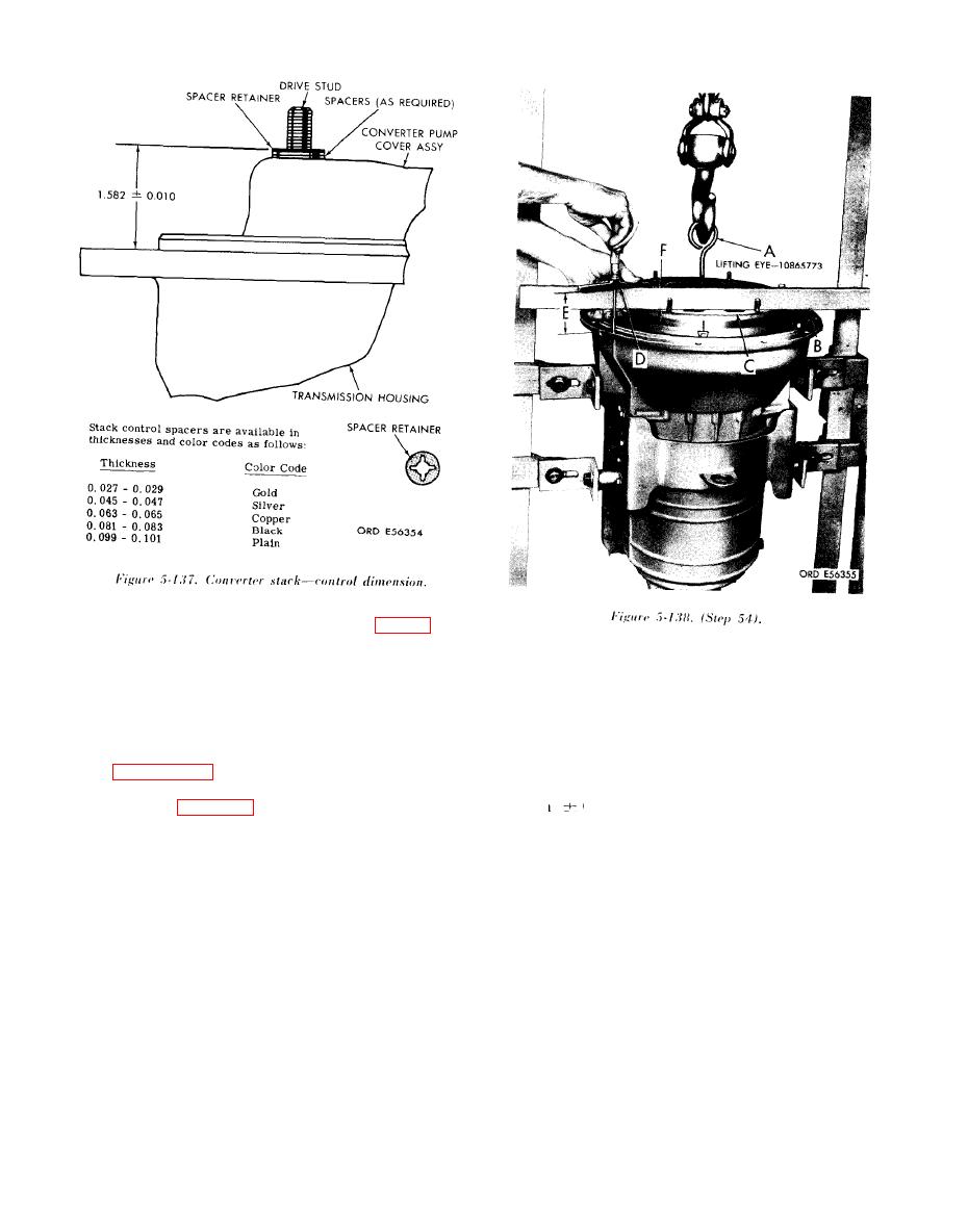 NOTE
The procedures outlined in step 54 (fig. 5-
Attach a hoist to lifting eye 4910-673-3801
138) are necessary to space the trans-
(10865773) (A) and apply sufficient lifting force
mission properly in relation to the trans-
(50 to 100 lb) to eliminate all end play. Position
mission driving disk (on engine or input
straight-edge (B) on converter pump cover (C), as
drive transfer gear). If correct spacing is
shown. Using a micrometer depth gage (D),
not established, the driving disk will be
measure and record dimension (E). Subtract height
subject to strains which will cause its
of straight-edge (dimension F) from dimension (E),
failure and possible transmission damage.
and record the difference. Subtract this difference
from 1.566 inches. Select spacers which will equal
stack control spacers, and spacer retainers.
(within 0.010) inch the resulting dimension.
Step 54 (fig. 5-138) outlines the methods
This is the proper spacer thickness to be used at the
for establishing the required spacing.
drive stud.
|
|
Privacy Statement - Press Release - Copyright Information. - Contact Us |
