 |
|||
|
|
|||
|
|
|||
| ||||||||||
|
|
 NOTE
Refer to paragraph 5-31a for proper
method of installing expander and seal
ring.
(4) Install high-range clutch piston assembly
(27) into housing (22). Make certain that piston
engages three drive pins in housing.
(5) Install inner and outer return springs (28
and 29) and retainer (30) in housing (fig. 5-70).
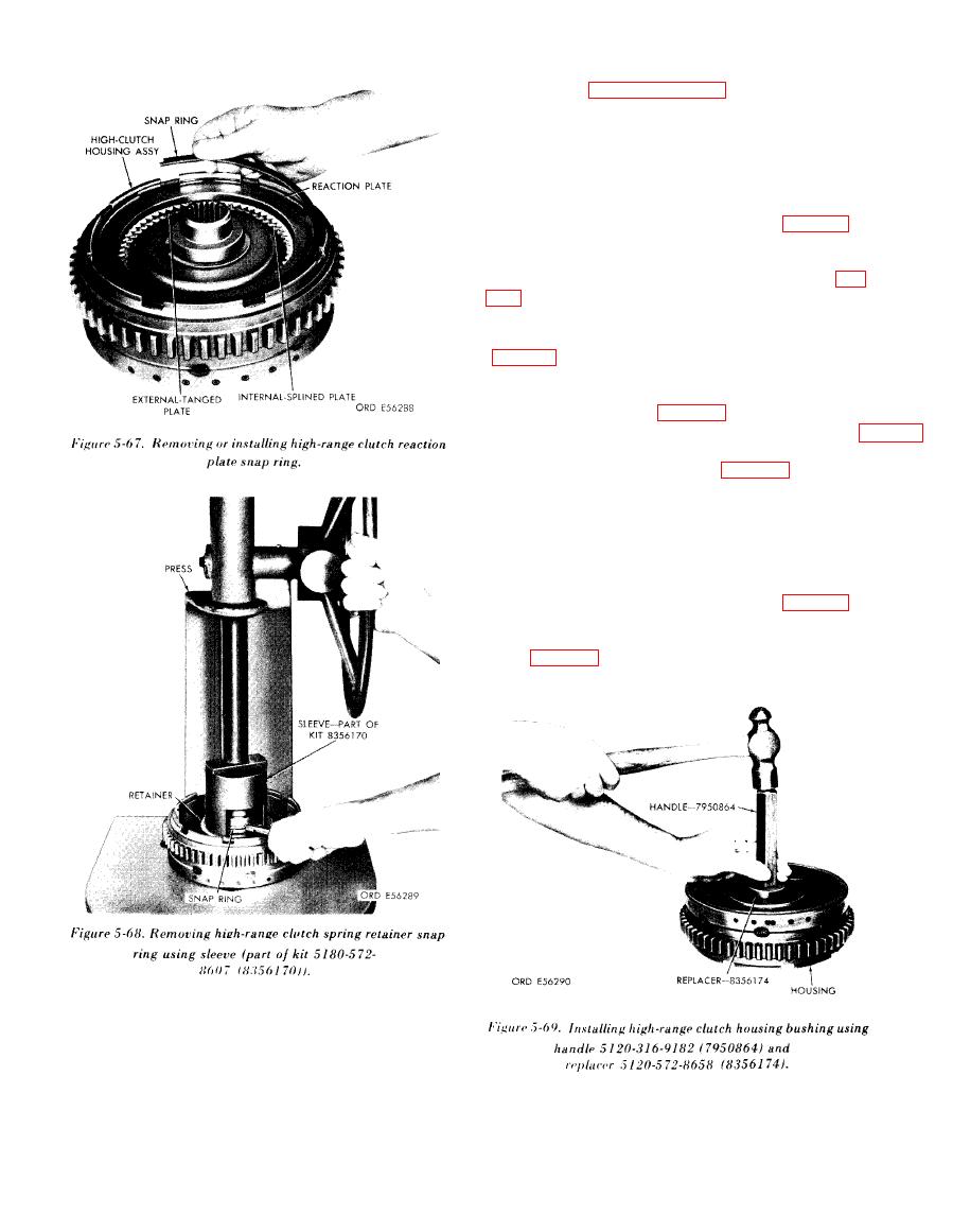
(6) Position guide, part of kit 5180-572-8607,
on housing hub. Position snap ring over guide, and
ring, part of kit 5180-572-8607, over snap ring (fig.
(7) Place sleeve, part of kit 5180-572-8607, on
ring and using a press, install snap ring in place
( 8 ) Starting with an internal-splined plate,
alternately install four internal-s plined and three
external-tanged plates (fig. 5-67).
(9) Install reaction plate and snap ring (fig. 5-
67).
(1) Install two hook-type seal rings (11) and
retainer snap ring (12) on shaft assembly (8).
(2) Insert long splined end of converter turbine
shaft assembly (8) in pitot collector side of high-
range clutch housing assembly (22).
(3) Install intermediate-range sun gear and
low-range sun gear on converter shaft (fig. 5-72).
(4) Using guide and driver, part of kit 2120-
572-8663, install snap ring to secure sun gear on
shaft (fig. 5-73).
(2) Install hook-type seal ring (24) in housing
(22).
(3) Install ring expander (26) and seal ring
(25) on piston (27).
|
|
Privacy Statement - Press Release - Copyright Information. - Contact Us |
