 |
|||
|
|
|||
|
Page Title:
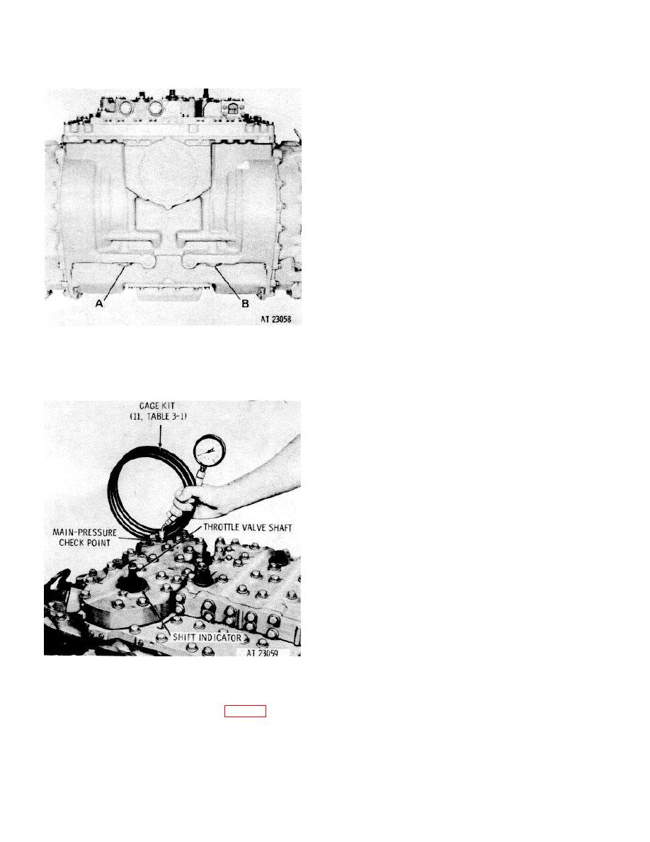
Figure 9-3. Transmission oil pressure check points-rear |
|
||
| ||||||||||
|
|
 TM 9-2520-249-34& P
(2) In all tests, the transmision sump
temperature should be normal (180 to 2200F).
Connect the pressure gage(s) to the check point(s)
indicated for the test being made.
(3) Reduce the speed of the transmission
input to engine idle speed before engaging the desired
range. Then slowly increase speed to the rpm desired.
Record the pressure reading for each test.
(4) Do not attempt to remove or install the
pressure gage(s) while the transmission is operating.
Tightly reinstall the plugs immediately upon removing
the gage(s)
(5) When making the tests for steer clutch
pressure, move the steer control from center to full steer
slowly while observing the pressure rise. Pressure
should be maximum at full-steer position.
(6) In test for lockup engagement with unit in
third gear, increase speed slowly until lockup apply
pressure registers. Record output speed which registers
at that time.
(7) In tests for lockup release with unit in third
A-Left brake coolant
gear, first increase the input speed to above the point
B-Right brake coolant
where lockup occurs. Observe lockup clutch apply
pressure while slowly reducing the speed until lockup
Figure 9-3. Transmission oil pressure check points-rear
pressure drops quickly. When pressure drops quickly,
view.
record the output speed.
(8) During all tests observe the left and right
transmission output rotation. Rotation should be as
outlined in e, below.
e. Rotation of Transmission Outputs.
(1) In all forward and reverse gears the
transmission outputs will tend to rotate even at engine
idle speeds. A light application of the brake will stop
such rotation when the transmission is functioning
properly.
(2) In all forward gears, the transmission
output should rotate clockwise as viewed from the right
side of the transmission when no steer is applied.
(3) In reverse gears, the transmission output
should rotate counterclockwise as viewed from the right
side of the transmission when no steer is applied.
(4) In first gear, during normal or pivot steer,
and in second and third gears during pivot steer, the
output at the side toward which the turn is made rotates
counterclockwise. The output at the opposite side
rotates clockwise. Both rotations are as viewed from the
right side of the transmission.
(5) In second, third and fourth gears during
normal steer, and in fourth gear during pivot steer, both
Figure 9-4. Checking transmission main pressure.
outputs rotate clockwise (as viewed from the right side
of the transmission). The output at the side toward
d. Functional Tests.
which the turn is made rotates slower than the output on
(1) The test data log sheet (fig. 9-1) can be
the opposite side.
used as a guide for making functional tests, as well as
providing spaces to record actual test results. In
addition, the normal pressures are included for
comparison with test results.
9-5
|
|
Privacy Statement - Press Release - Copyright Information. - Contact Us |
