 |
|||
|
|
|||
|
Page Title:
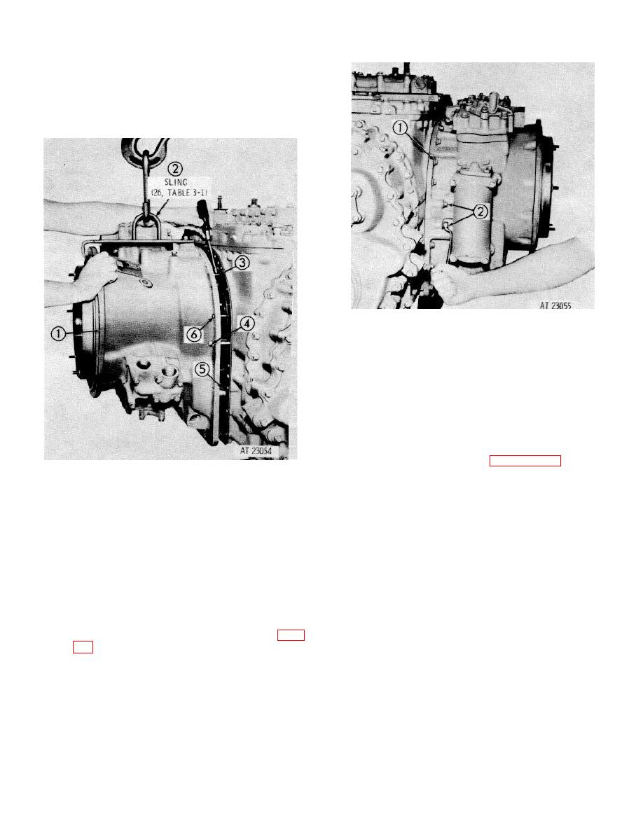
Position converter housing assembly |
|
||
| ||||||||||
|
|
 TM 9-2520-249-34& P
NOTE
Be careful that low-range clutch disks (3),
springs (2) and spring pins (1) do not fall
out of the housing.
The low-range
planetary carrier assembly splines (5) must
engage bevel gear carrier splines (6).
125 Install twenty-one /8- 16 x 1 5/8-inch bolts (1).
two 3/8-16 x 2 3/4-inch bolts (2), 23 plain
washers and 23 lockwashers. Install one 3/8-16
x 3 1/4-inch bolt at the top of the converter
housing, and install one plain washer and one
lockwasher. Tighten 24 bolts to 27 to 32 pound
feet torque. Install oil filler and level indicator
kit (62, foldout 101.)
NOTE
To establish the oil level in the power train
following overhaul. refer to paragraph 9-4b (6)
124 Position
converter
housing
assembly
(1)carefully on guide bolts (6), being careful not
to damage oil suction tube (5). Install two 3/8-
16 x 2 3/4-inch bolts (4), 180 degrees to each
other, and, while making repeated checks to
ensure that the clutch plates are in position and
the springs and pins (3) are perpendicular to the
piston face, draw the converter housing toward
the bevel gear housing. Install two 3/8-16 x 1
5/8-inch bolts, two plain washers and two
lockwashers, 180 degrees to each other and
draw the converter up completely to the bevel
gear housing. Remove the two guide bolts and
the two draw bolts. Remove sling (2), (26, table
8-42
|
|
Privacy Statement - Press Release - Copyright Information. - Contact Us |
