 |
|||
|
|
|||
|
|
|||
| ||||||||||
|
|
 TM 9-2520-249-34& P
116
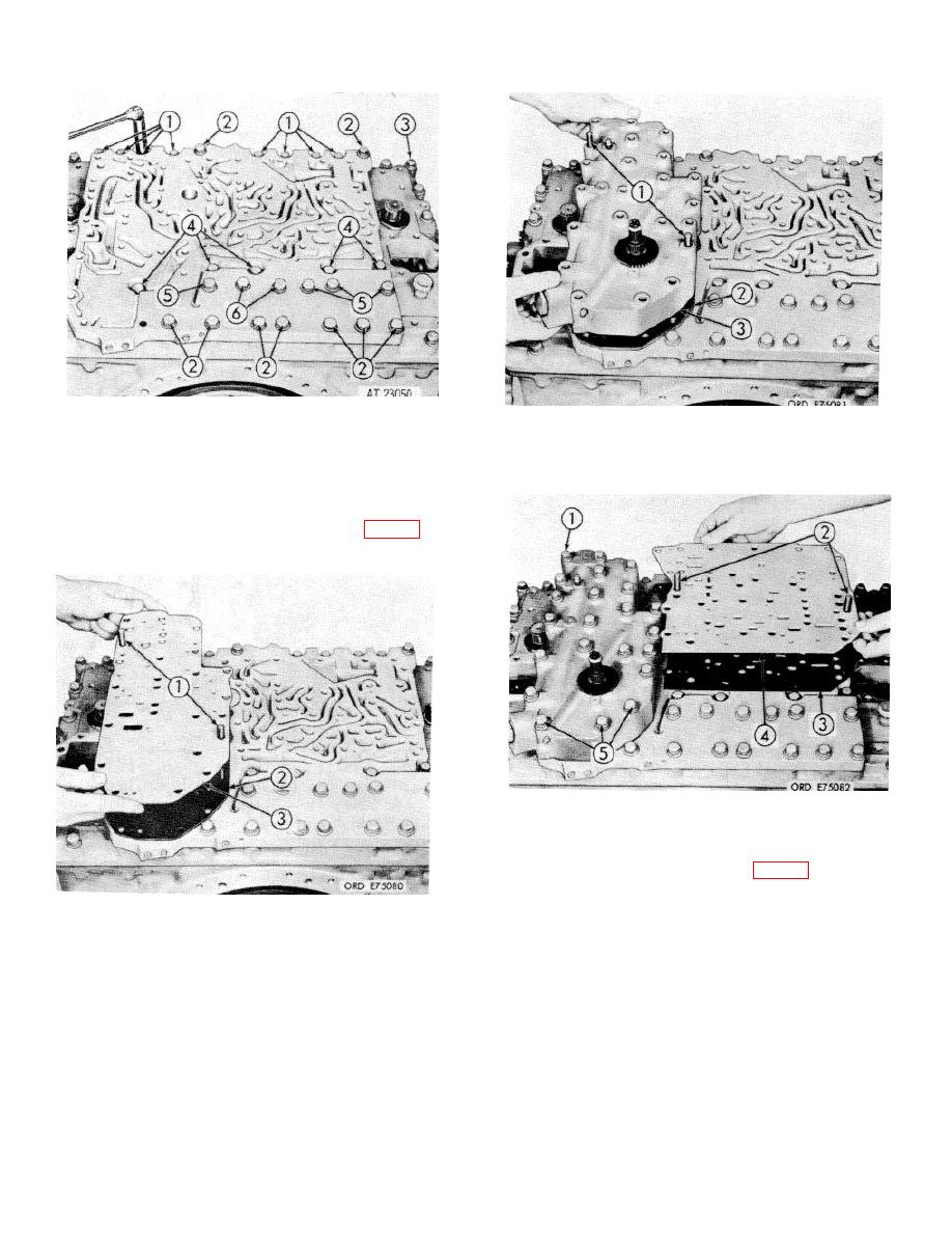
Remove the guide bolts and install nine 3/8-16
x 3 1/4-inch bolts (2), four 3/8-16 x 1 3/4-inch
118 Install gasket
(2) and control valve body
bolts (5), two 3/816 x 2-inch bolts (6), five 3/8-
assembly (3) over guide bolts (1). Remove
16 x 1 1/4-inch bolts (4), eight 3/8-16 x 2 5/8-
guide bolts.
inch bolts (1), 28 plain washers and 28
lockwashers. Tighten the bolts to 20 to 24
pound feet torque. Tighten 14 bolts (3) to 20 to
24 pound feet torque. Refer to FO-15 for
correct sequence of tightening these bolts.
119 Install three 3/8-16 x 51/4-inch bolts (5),
nineteen 3/8-16 x 3 3/4-inch bolts (1) 22 plain
washers and 22 lockwashers in the control valve
body assembly. Refer to FO-15 for proper
method and sequence of tightening the bolts. In
stall two 3/8-16 x 4-inch guide bolts (2) in the
117 Install two 3/8-16 x 4-inch, headless guide bolts
steer valve mounting pad. Install gasket (3) and
(1) in the control valve body mounting pad.
separator plate (4) over the guide bolts.
Install control valve body gasket (2) and
separator plate (3) over the guide bolts.
8-40
|
|
Privacy Statement - Press Release - Copyright Information. - Contact Us |
