 |
|||
|
|
|||
|
|
|||
| ||||||||||
|
|
 TM 9-2520-249-34&P
up and down by squeezing the sling strands
together. This movement allows the internal
splines of the steer clutch disks to engage the
splines on the output clutch hub and thus seat
properly. Two slots in oil baffle 31 must be
engaged with two keys (41, positioned 180
degrees apart. Remove lifting sling (1).
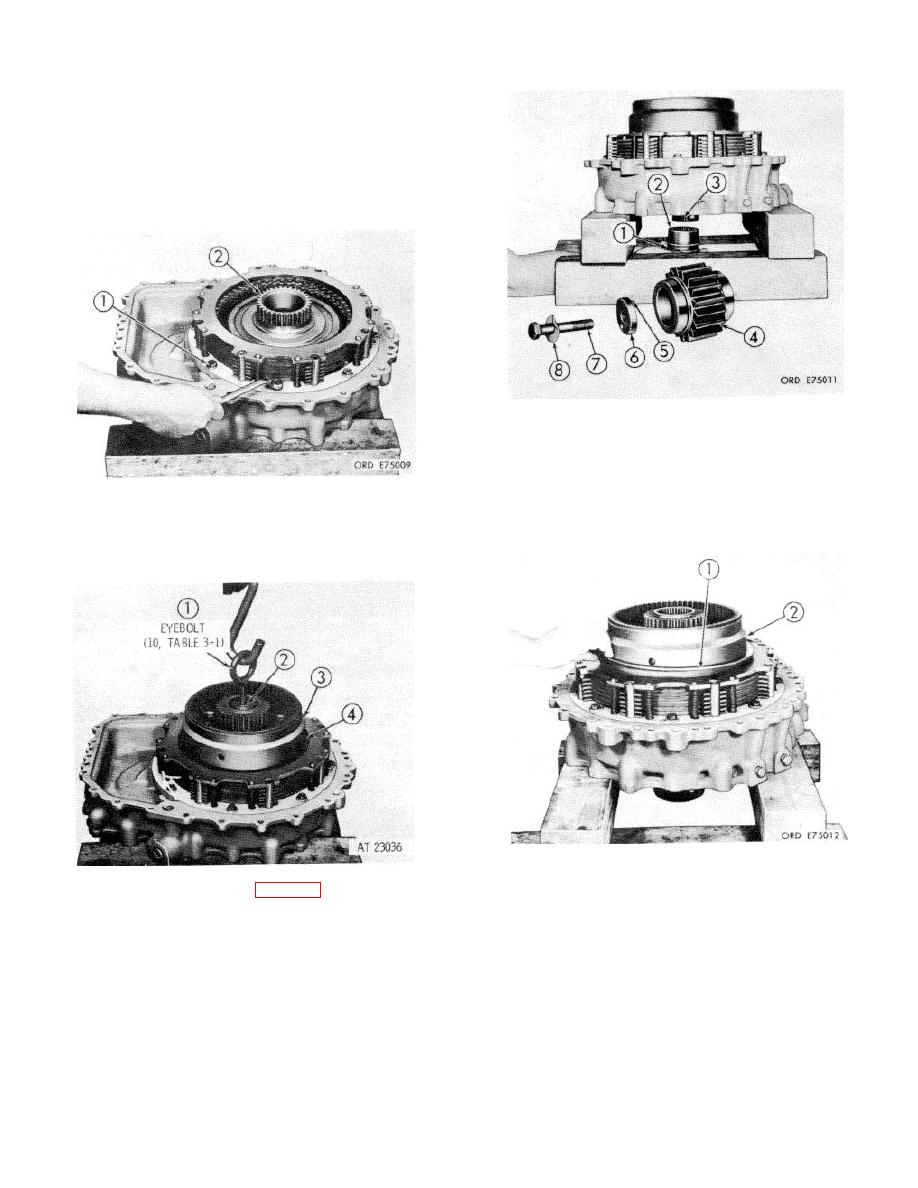
48 Install two sealrings (1) onto splined sleeve (2).
Install, in succession, splined sleeve (2), plain
end first, output drive gear (4), lock plate
assembly (6) with pin (5) toward the gear,
lockwasher (8) and bolt (7), holding each part in
place with one hand until bolt (7) is engaged in
46 Install eight 3/8-16 x 2 1/4-inch, self-locking
threads in output shaft (3). Tighten the bolt only
bolts (1) and eight plain washers. Tighten the
finger tight at this time.
bolts to 36 to 43 pound feet torque. Note sun
gear (2). Refer to step 47, below.)
49 Install oil baffle (1) on brake hub (2).
47 Insert eyebolt (1) (10, table 3-1) into the end of
output shaft (2) and install the output shaft.
steer planetary carrier and brake hub as a unit.
The splines of brake hub (3) must engage the
internal-splined brake disks at (4). Also sun
gear 12, step 40, above must engage the steer
planetary pinions in the unit. Remove eyebolt
(1).
8-20
|
|
Privacy Statement - Press Release - Copyright Information. - Contact Us |
