 |
|||
|
|
|||
|
Page Title:
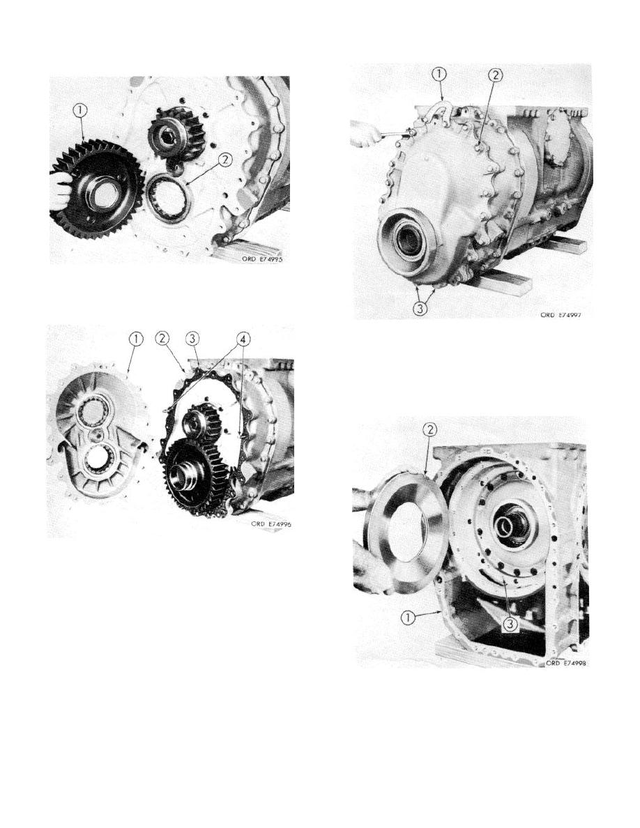
Install left output driven gear |
|
||
| ||||||||||
|
|
 TM 9-2520-249-34&P
32. Install left output driven gear (1) into bearing (2).
The short hub (plugged end) of the gear faces
the output housing.
34. Install lifting bracket I1I, nineteen /8-16 x 2 1/4-
inch bolts (2), tow 3/8-16 x 21/2-inch bolts
(3)1, 21 plain washers and 21 lockwashers. The
two bolts (3) at bottom install from the output
housing into the end cover. Tighten to 27 to 32
pound feet torque.
33. Install two 3 / 8-16 x 4-inch, headless guide
bolts (41 into output housing (2), 180 degrees
apart. Install gasket (3). Install end cover
assembly (1). Remove guide bolts (4).
35. On the right side of bevel gear housing (1),
install reverse-range clutch piston (2), with its
seal rings. Note hole (3): refer to step 36,
below.
8-16
|
|
Privacy Statement - Press Release - Copyright Information. - Contact Us |
