 |
|||
|
|
|||
|
Page Title:
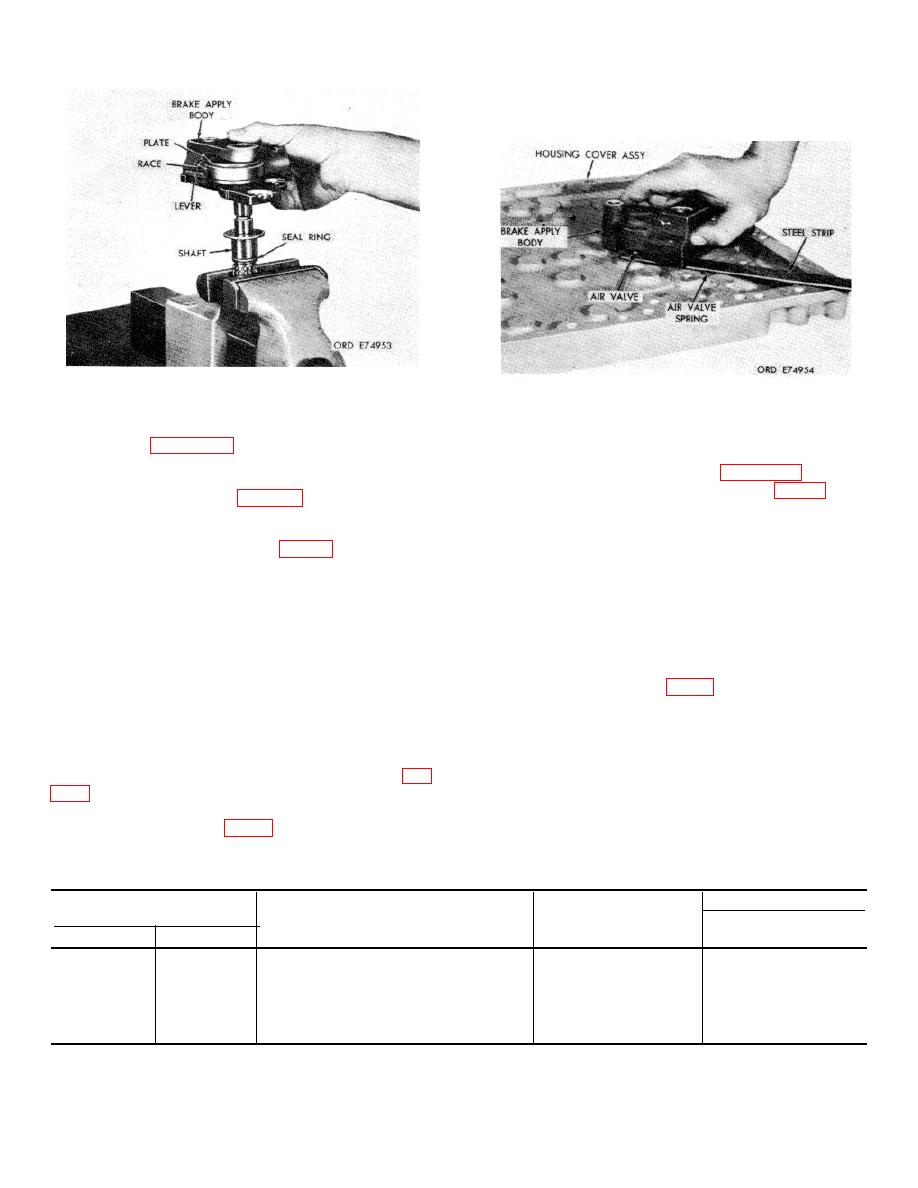
Figure 7-62. Removing (or installing) brake apply shaft. |
|
||
| ||||||||||
|
|
 TM 9-2520-249-34&P
holes provided in cover (37) and brake apply shaft (74).
Remove the steel strip.
Figure 7-62. Removing (or installing) brake apply shaft.
Figure 7-63. Installing brake apply assembly.
m. Install the sealring onto the brake apply
u. Secure brake apply body assembly (79) to
shaft. Refer to figure 7-62.
housing cover (37) with two bolts (93), two bolts (85) and
n. With the brake apply shaft held in a soft
their washers (94 and 84). Refer to figure 7-60.
jaw vise, install the brake apply body with components
onto the brake apply shaft (fig. 7-62). Rotate the splined
two retaining rings (29) on brake apply shaft (74).
brake lever, cam and plate to index with the blind spline
NOTE
on the brake shaft.
Repeat procedures outlined in c through v,
above,
to
assemble
and
install
apply shaft (74) and secure it with retaining ring (91).
corresponding components making up the
p. If seal (77) was removed from air valve
right brake apply mechanism. However,
(78), install a new seal.
rotation to index spring (46) will be
q. Install air valve assembly (76), smaller
clockwise instead of counterclockwise as for
diameter first, into brake apply valve body (82).
spring (73) in t, above.
r.
Install spring (75) into housing cover (37).
w. Install the right and left brake adjustment
s. Install spring (73) into housing cover (37),
access covers (40 and 24, FO-13) with gaskets (39 and
making sure that the end of the spring is engaged with
23) temporarily onto housing cover (37) and secure with
the hole in the cover.
six capscrews (44 and 28), lockwashers (42 and 26) and
t.
Using a smooth thin steel strip to compress
flat washers (41 and 25).
the air valve spring and hold the air valve assembly in
x. Install breather assembly (35) into housing
the brake apply body, install the brake apply body and
cover (37).
its component parts on the housing cover assembly (fig.
strip positioned, in a counterclockwise direction so that
the ends of spring (73, FO-13) are indexed with the
Table 7-27. Repair Standards (Right, Left Brake Apply body Bevel Gear Housing Cover)
Wear limit
Reference
Size and fit
DS/GS
Foldout
Item
Point of measurement
of new parts
maintenance
13
46a
Free position of spring ends..................
123 apart
*
13
46a
Position under torque load
45 at 12.9 to 15.7
45 at 12.2 lb
in. lb
13
47a
Diameter at smaller end of shaft ...........
0.6245 to 0.6250
0.6243
13
47a
Diameter at center bearing surface of shaft 0.7495 to 0.7500
0.7493
*See footnote at the end of table.
7-61
|
|
Privacy Statement - Press Release - Copyright Information. - Contact Us |
