 |
|||
|
|
|||
|
|
|||
| ||||||||||
|
|
 TM 9-2520-249-34&P
b. Assemble and install the right and left
NOTE
brake apply body assemblies as outlined in c through v,
The right and left brake apply valve body
below.
assemblies are identical except that they
c. If pins (80) were removed from brake apply
are designed for opposite sides, therefore,
body (82), install new ones. Press pins (81) into body
e through o, below, will apply to either one.
(82), 0.060 inch below the surface of the body and stake
The instructions are keyed to the left brake
securely.
apply body (FO-13, items 72 through 98).
d. If bearing (83) was removed from brake
e. Remove preformed packing (72) from
apply body (82), install a new bearing. Install the
brake apply shaft (74).
bearing, pressing against the numbered side, 0.060 to
f.
Remove springs (73 and 75) from cover
0.070 inch above the oil port relief surface of the body.
assembly (36).
e. If bearing (80) was removed from brake
g. Remove air valve assembly (76) from
apply body (82), install a new bearing. Install the
brake apply body (82). Do not remove seal (77) from air
bearing, pressing against the numbered side of the
valve (78). except for replacement.
bearing, flush with, to 0.010 inch below, the surface of
h. Remove retaining ring (91) and washer (92)
the body .
from brake apply shaft (74).
f.
Install signal valve (95), small end first, into
i.
Remove brake apply shaft (74, FO-13)
brake apply body (82).
from brake apply body (82). Refer to figure 7-62.
g. Install signal valve spring (96) and washer
j.
Remove lever (86. FO-13), cam (88),
(97) into brake apply body (82) and secure washer (97)
rollers (90), bearing race (87), and plate (89) from brake
with retaining ring (98).
apply body (82).
h. Apply a coating of oil-soluble grease to
k. Remove retaining ring (98) from brake
needle bearing race (87), cam (88,) and rollers (90).
apply body (82).
i.
Place the brake apply cam side plate (89)
l.
Remove flat washer (97, FO-13), spring
on the assembly table and position brake cam (88) on
(96) and valve (95) from brake apply body (82).
the plate. Refer to figure 7-61.
m. Do not remove bearing (80 or 83) from
brake apply body (82) except for replacement.
n. Do not remove pins (81) from the brake
apply body (82) except for replacement.
o. Do not remove hexagon-head plugs 138)
from cover (37) except for replacement.
7-190. Cleaning
Refer to paragraph 5-2 for cleaning recommendations.
7-191. Inspection and Repair
Refer to paragraph 5-3 for inspection and repair
recommendations.
7-192. Repair Standards
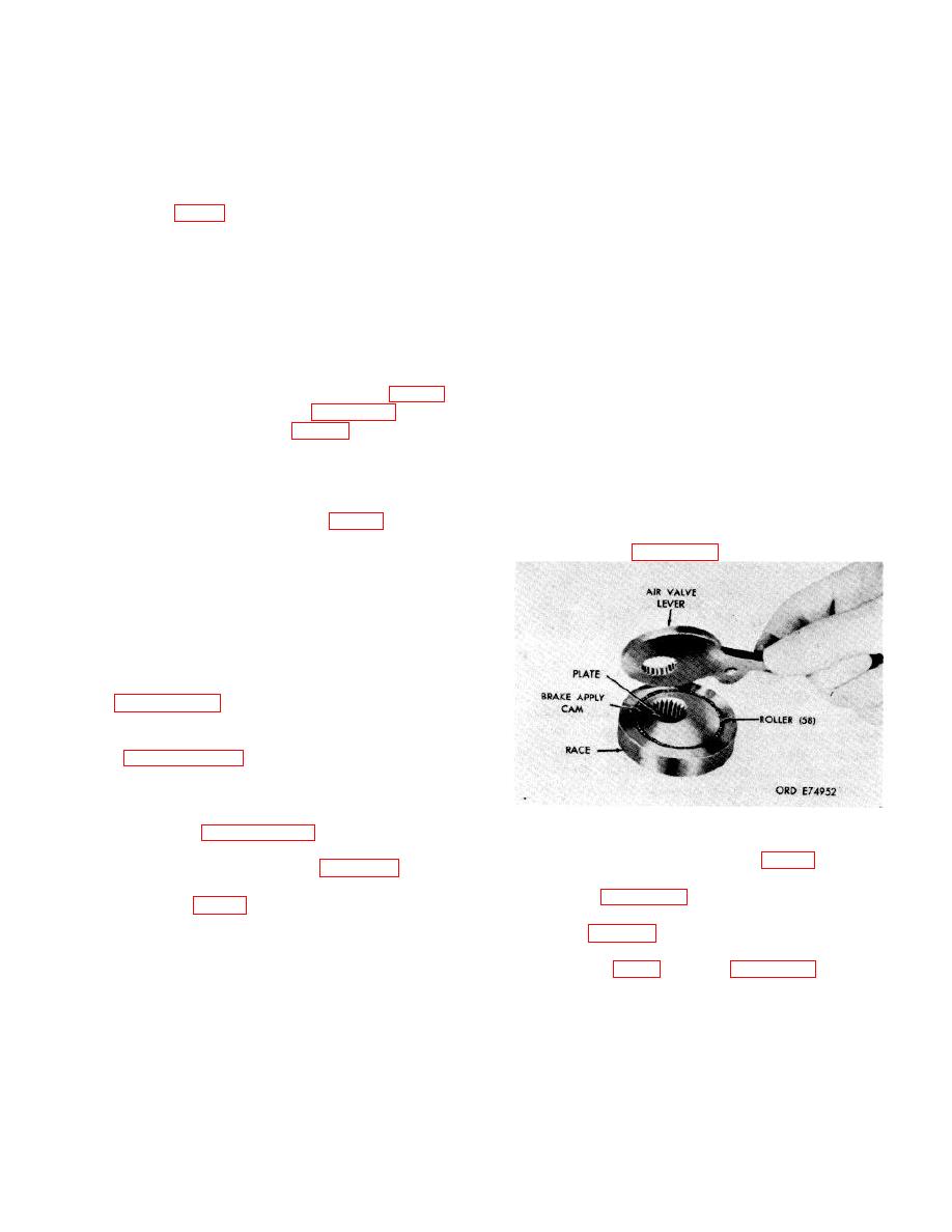
Figure 7-61. Components of left brake assembly,
showing relation of parts.
repair standards.
j.
Place bearing race (87, FO-13) over cam
(88) and install 58 rollers (90) between the cam and
race. Refer to figure 7-61.
k. Place the brake air valve lever onto the
a. If hexagon-head plugs (38) were removed
components (fig. 7-61), as shown.
from housing cover (37), install plugs.
l.
Install the brake components into the brake
apply body (82, FO-13). Refer to figure 7-62
7-60
|
|
Privacy Statement - Press Release - Copyright Information. - Contact Us |
