 |
|||
|
|
|||
|
Page Title:
Section XXXI. OIL TRANSFER PLATE ASSEMBLY-REPAIR |
|
||
| ||||||||||
|
|
 TM 9-2520-249-34&P
Table 7-26. Repair Standards (Steer Valve Body)-Continued
Wear limit
Reference
Size and fit
DS/GS
Foldout
Item
Point of measurement
of new parts
maintenance
12
117a
Free length of spring ............................
2.075
*
12
117a
Length under load ...............................
1.22 at 28.5 to
1.22 at 27.5 lb
31.5 lb
*Replace when worn beyond new dimensions.
Section XXXI. OIL TRANSFER PLATE ASSEMBLY-REPAIR
7-185. Inspection and Repair
7-182. Description
Refer to paragraph 5-3 for inspection and repair
The oil transfer plate has numerous oil passages and
recommendations.
channels to connect passages of control valve bodies
and transmission housings. Refer to paragraph 2-27.
7-186. Repair Standards
No repair standards apply to these components.
Do not remove threaded plugs (16, 17 and 20) except
for replacement or cleaning.
If threaded plugs (16, 17 and 20) were removed, install
7-184. Cleaning
them, if serviceable, or install new plugs.
Refer to paragraph 5-2 for cleaning recommendations.
Section XXXII. RIGHT AND LEFT BRAKE APPLY BODY AND BEVEL GEAR HOUSING COVER ASSEMBLIES-
REPAIR
7-188. Description
The manually operated right and left brake apply bodies
and associated parts mechanically apply the brakes.
Applying the brakes causes the brake coolant pump to
provide oil to cool the brakes. The bevel gear housing
cover provides a mounting for the brake apply
components and control valve bodies.
Refer to
a. Remove breather assembly (35) from
cover assembly (36).
b. Remove right and left brake adjustment
access covers (24 and 40) with gaskets (23 and 39).
c. Remove four retaining rings (21 and 29)
and indicator keyed washers (22 and 30) from both right
and left brake apply shafts (47 and 74).
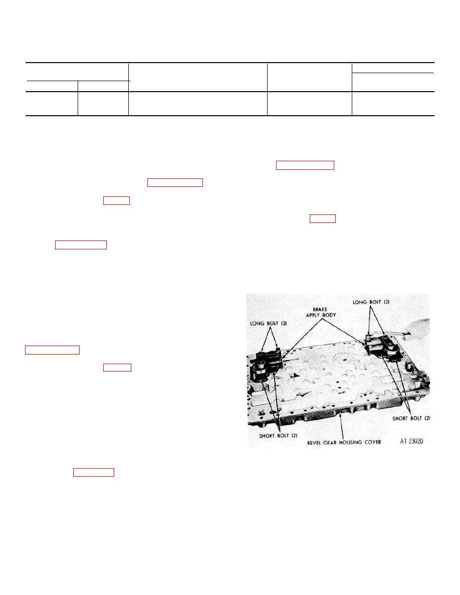
d. Remove eight bolts (62, 65, 85, 93) and
washers (61, 66, 84, 94). Remove the right and left
brake apply body assemblies (52 and 79) from housing
Figure 7-60. Removing (or installing) brake apply body
Removing (or installing) brake apply body bolt. cover
bolt
(37). Refer to figure 7-60.
7-59
|
|
Privacy Statement - Press Release - Copyright Information. - Contact Us |
