 |
|||
|
|
|||
|
Page Title:
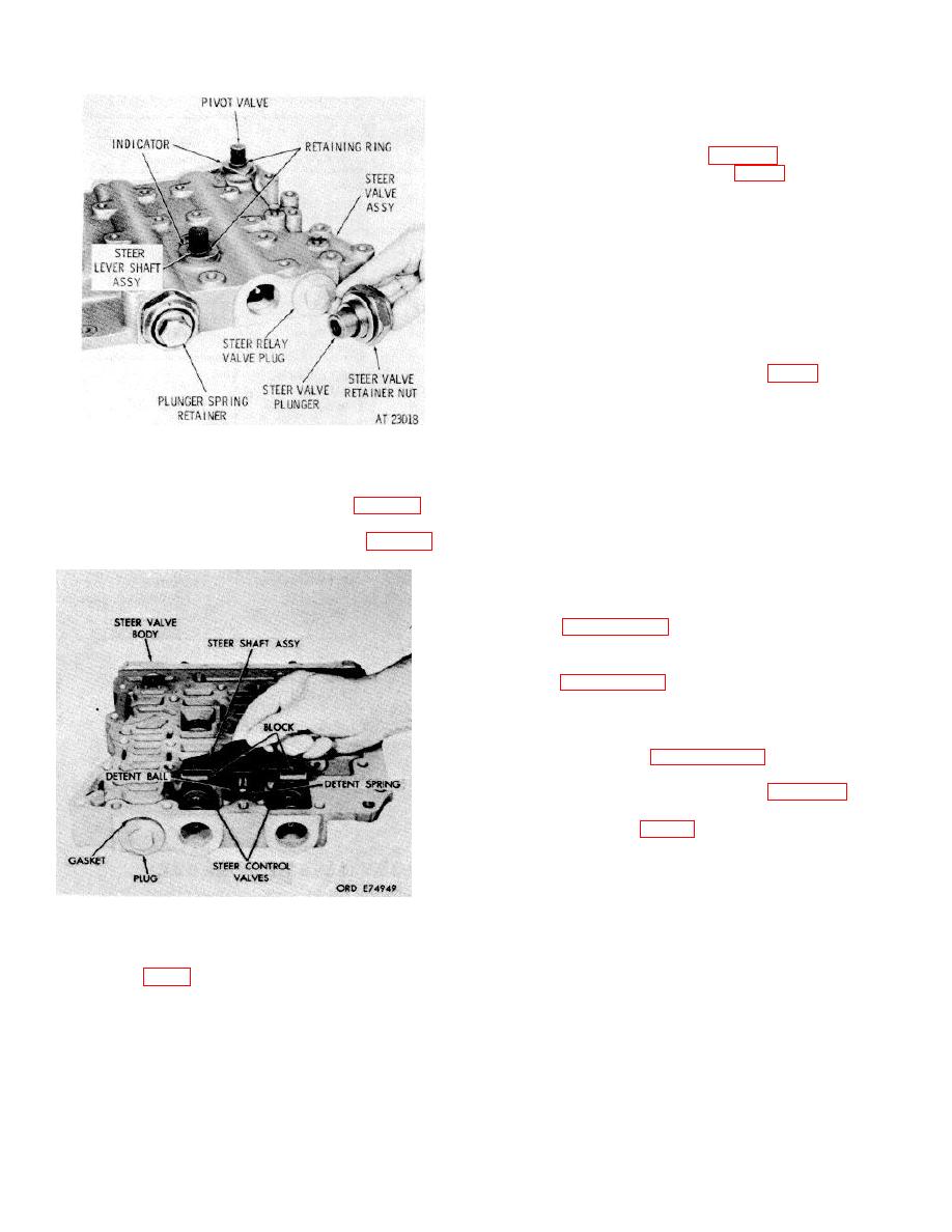
Figure 7-58. Removing for installing) steer shaft assembly |
|
||
| ||||||||||
|
|
 TM 9-2520-249-34&P
valve stems (81 and 108) from steer regulator valves
(82 and 107).
f.
Remove the steer relay valve plug and
gasket from steer valve body (fig. 7-57).
plug valve (74).
h. Remove 12 bolts (55 and 122), flat washers
(57 and 120) and lockwashers (56 and 121) which retain
cover (119). Remove valve body cover (119) and
gasket (118) from valve body (109).
i.
Remove detent spring (59), detent ball (60)
and drive relay valve spring (117) and stop pin (58).
j.
Remove drive relay valve (116).
k. Remove retaining rings (66 and 67) and
pivot valve indicator (65) from pivot valve (63).
l.
Remove pivot valve (63, FO-12) from steer
valve body (109).
m. Remove preformed packing (64) from steer
valve body (109).
n. Remove plugs (68) from steer valve body
Figure 7-57. Removing (or installing) steer valve plunger
(109).
and related parts.
o. Do not remove dowel pin (62) unless
b. Remove retaining rings and indicators from
replacement is necessary.
pivot valve and steer lever shaft assembly (fig. 7-57)
p. Do not remove detent sleeve (111) unless
c. Remove steer shaft assembly, blocks,
replacement is necessary.
detent hall and spring from steer valve body (fig. 7-58)
(73) unless replacement is necessary.
7-178. Cleaning
Refer to paragraph 5-2 for cleaning recommendations.
7-179. Inspection and Repair
Refer to paragraph 5-3 for general inspection and repair
recommendations.
7-180. Repair Standards
repair standards.
steer valve body (109), install new replacements. Install
one needle bearing into top of the valve body, pressing
against the numbered side of the bearing cage, 0.200
inch below the surface adjacent to the bearing bore of
Figure 7-58. Removing for installing) steer shaft
the valve body. Install the remaining bearing (73),
assembly.
pressing against the numbered side of bearing cage,
d. Remove steer control shaft preformed
from the bottom side of the valve body, 0.150 inch
packing (72, FO-12) from steer valve body (109).
below the surface adjacent to the bearing bore of the
e. Remove steer valve assemblies (79 and
valve body.
100).
Do not disassemble these parts unless
b. If detent sleeve (111) was removed, install
replacement is necessary. If necessary, remove nuts
it from the lower side of steer valve body (109). Press
187 and 101), steer valves (86 and 102) and steer
the sleeve to 0.241 to 0.251 inch below the valve body
regulator valve springs (103 and 104), and (84 and 85)
mounting surface.
from steer regulator valve assemblies (80 and 106).
Remove stops (83 and 105). Remove steer regulator
7-56
|
|
Privacy Statement - Press Release - Copyright Information. - Contact Us |
