 |
|||
|
|
|||
|
Page Title:
Section XXVII. INPUT OIL PUMP ASSEMBLY-REPAIR |
|
||
| ||||||||||
|
|
 TM 9-2520-249-34&P
a. If plug (85) was removed from valve body
spring (81) from valve body (84).
(84), install a new replacement part.
e. Do not remove plug (85) unless
b. Install cooler bypass valve spring (81) onto
replacement of parts is necessary.
If necessary,
seat (79). Install the spring and seat, spring end first,
remove the plug.
into the valve body.
c. Install bypass valve ball (77).
d. Install bypass valve seat (75), chamfered
7-154. Cleaning
inside diameter side first, into valve body (84).
Refer to paragraph 5-2 for cleaning recommendations.
e. Install retaining ring (74).
f.
Install lubrication regulator valve seat (83),
7-155. Inspection and Repair
flat side first, into valve body (84).
Refer to paragraph 5-3 for general inspection and repair
g. Install retaining ring (82).
recommendations.
h. Install lubrication regulator valve (80), large
end first, and spring (78).
7-156. Repair Standards
i.
Install valve guide (76), small diameter
first, onto valve (80) and against valve spring (78) in
repair standards.
valve body (84). Secure guide (76) with retaining ring
(74). Refer to figure 7-54.
7-157. Assembly (FO 10)
Table 7-22. Repair Standards (Lubrication Regulator Valve
Wear limit
Reference
Size and fit
DS/GS
Foldout
Item
Point of measurement
of new parts
maintenance
10
78a,
Free length of spring.............................
2.16
*
81a
10
78a,
Length under load ................................
1.16 at 10.50 to
1.16 at 10.25 lb
81a
11.50 lb
*Replace when worn beyond new dimensions.
Section XXVII. INPUT OIL PUMP ASSEMBLY-REPAIR
7 -158. Description
Refer to paragraph 2-2 for description of the input oil
pump components.
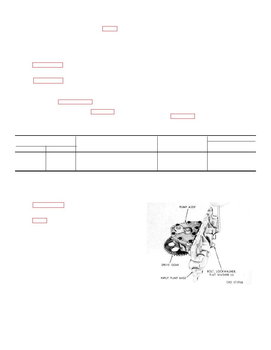
7-159. Disassembly
washers, and input pump base with gasket from the
input pump body. Refer to figure 7 55.
Figure 7-55 Removing for installing) input
pump base bolt.)
7-49
|
|
Privacy Statement - Press Release - Copyright Information. - Contact Us |
