 |
|||
|
|
|||
|
Page Title:
Section XXIV. OIL FILTER ASSEMBLY-REPAIR |
|
||
| ||||||||||
|
|
 TM 9-2520-249-34&P
Section XXIV. OIL FILTER ASSEMBLY-REPAIR
7-140. Description
7 -141. Disassembly
Refer to paragraph 2-20 for description of the oil filter
assembly.
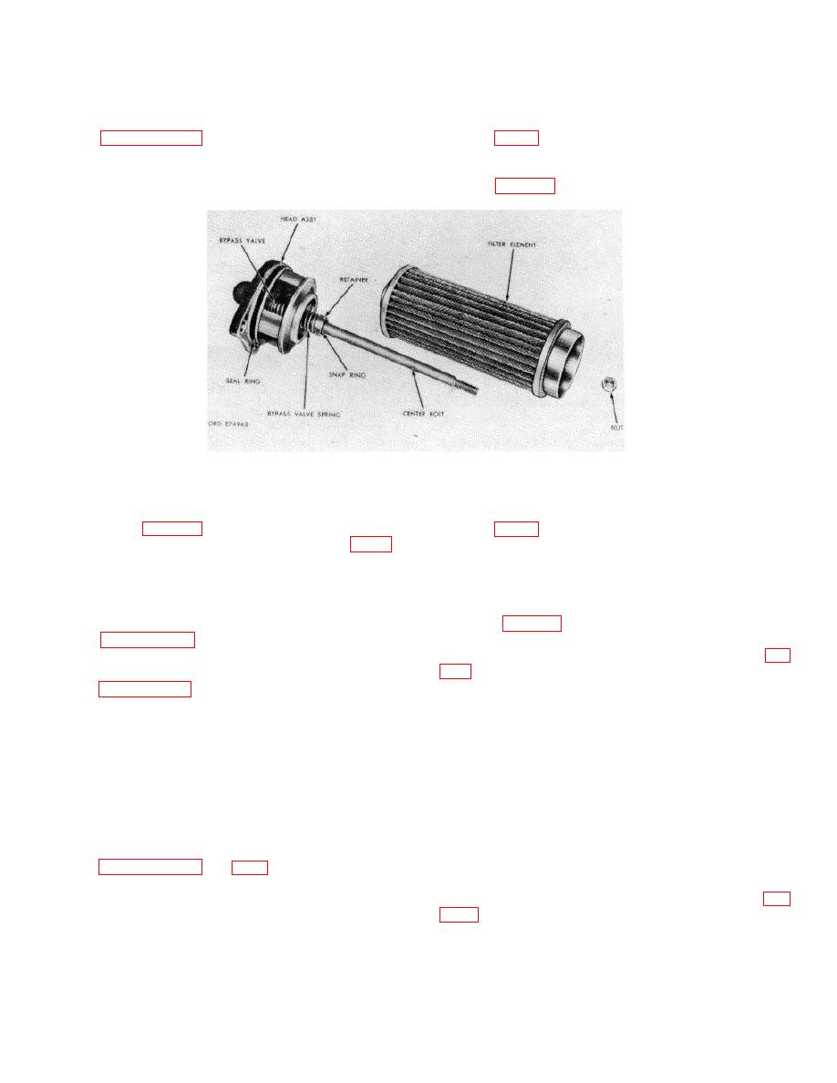
a. Remove the nut from the filter assembly
and separate the filter head assembly from the oil filter
element (fig. 7-51).
Figure 7-51. Oil filter assembly components.
b. Remove the filter sealring from the filter
7-145. Assembly
head assembly (fig. 7-51).
a. If screw thread inserts (7) were removed
10) from filter housing (8), unless replacement of parts
from housing (8), install new replacement parts. Install
is necessary.
If necessary, remove screw thread
the inserts 0.005 inch, to one turn, below the surface of
inserts.
housing (8).
b. Install the filter sealring onto the filter head
assembly (fig. 7-51).
7-142. Cleaning
c. Install the filter head assembly onto the
Refer to paragraph 5-2 for cleaning recommendations.
filter element and retain it with the self-locking nut (fig.
7-143. Inspection and Repair
Refer to paragraph 5-3 for general inspection and repair
recommendations.
7-144. Repair Standards
No repair standards are involved in this assembly.
Section XXV. MAIN-PRESSURE REGULATOR VALVE BODY,
LOCKUP REGULATOR VALVE BODY ASSEMBLY, AND
OIL TRANSFER PLATE ASSEMBLY-REPAIR
7-146. Description
7 -147. Disassembly
Refer to paragraphs 2-21 and 2-27 for description of the
(FO 10)
main-pressure regulator valve body assembly, lockup
regulator valve body assembly, and oil transfer plate
eight flat washers from the valve body assembly (fig.
assembly.
from the valve body.
7-45
|
|
Privacy Statement - Press Release - Copyright Information. - Contact Us |
