 |
|||
|
|
|||
|
Page Title:
Section XXIII. OUTPUT OIL PUMP ASSEMBLY-REPAIR |
|
||
| ||||||||||
|
|
 TM 9-2520-249-34&P
Make certain the bearings are fully seated when
staking pins (52) were removed, install new replacement
installed.
parts. If two screw thread inserts (47) and staking pins
(48) were removed, install new replacement parts as
NOTE
follows: Select inserts for 0.002-inch tight to 0.002-inch
The cutout on the bearing race must
loose fit. Install to the dimension given in figure 7-47.
be indexed with the retaining plate
Use a bolt with same thread size as the inner thread of
location in the cover.
the insert, and a sleeve with an outside diameter smaller
f.
Install retaining plate (43) with tab
than the outside diameter of the insert, to install the
lockwasher (42) and bolt (41). Make certain the tab of
inserts. The bolt should project through the sleeve 1
the lockwasher that is bent at a right angle is inserted in
inch for the 5/16-18 bolts and 1 1/4 inch for the 3/8-16
the hole of the retaining plate. Bend the remaining two
bolts.
tabs against the flat sides of the bolt head.
e. If reduction drive and driven gear roller
g. If oil seal (6) was removed from
bearings (15 and 40, FO-8) were removed, install new
speedometer drive cover (4), install a new replacement
replacement parts. Chill the bearings in dry ice for 4
part. Press the seal, spring side last, until it bottoms.
hours and heat the cover to 3500 F before installation.
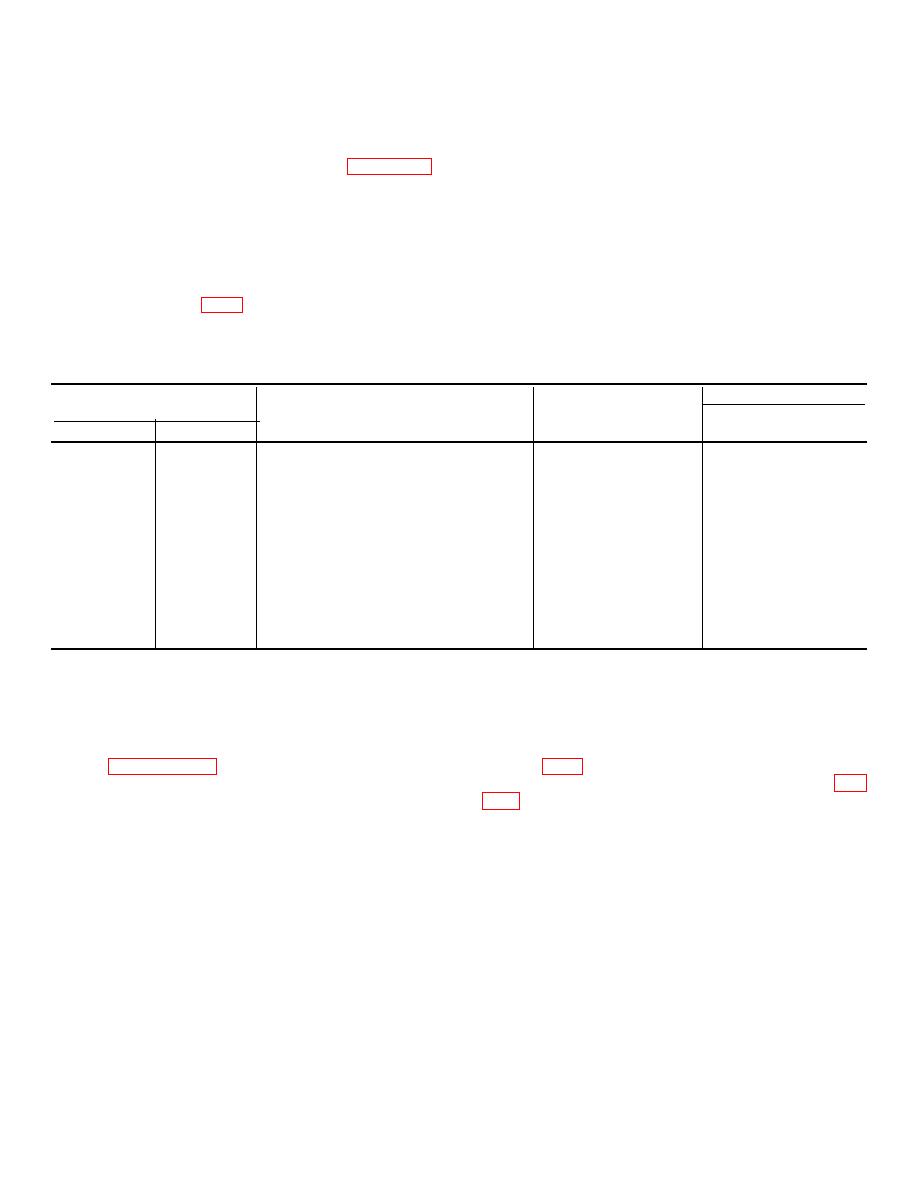
Table 7-19. Repair Standards Right Output End Cover, Speedometer Drive Cover)
Wear limit
Reference
Size and fit
DS/GS
Foldout
Item
Point of measurement
of new parts
maintenance
8
15a
Outside diameter of bearing .................
5.5133 to 5.5141
*
8
46b
Inside diameter at bearing surface of cover 5.5106 at 5.5118
5.5123
8
15a
Fit of bearing in cover ...........................
0.0015T to 0.0035T
46b
8
20a
Outside diameter at bearing surface of gear 3.7518 to 3.7528
*
8
40a
Outside diameter of bearing .................
5.5133 to 5.5141
*
8
46a
Inside diameter at bearing surface of cover 5.5106 to 5.5118
5.5123
8
40a
Fit of bearing in cover ...........................
0.0015T to 0.0035T
46a
8
49a
Outside diameter of sleeve installed .....
7.999 to 8.003 7.990
*Replace when worn beyond new dimensions.
Section XXIII. OUTPUT OIL PUMP ASSEMBLY-REPAIR
7-134. Description
7-135. Disassembly
Refer to paragraph 2-18 for description of the output oil
pump assembly.
7-43
|
|
Privacy Statement - Press Release - Copyright Information. - Contact Us |
