 |
|||
|
|
|||
|
Page Title:
Section XX. RIGHT AND LEFT OUTPUT HOUSING ASSEMBLY-REPAIR |
|
||
| ||||||||||
|
|
 TM 9-2520-249-34& P
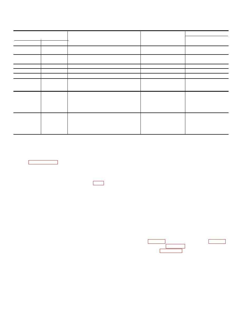
Table 7-16. Repair Standards (Right, Left Output Clutch Assemblies)-Continued
Wear limit
Reference
Size and fit
DS/GS
Foldout
Item
Point of measurement
of new parts
maintenance
8
99b
Inside diameter of piston housing at seal-
7.875 to 7.881
7.885
rings................................ .....................
8
99a
Inside diameter of housing sleeve at seal-
3.750 to 3.752
3.7540
rings................................ .....................
8
104a
Inside diameter of piston at sealring .....
4.500 to 4.502
4.5040
8
105a
Thickness of disk................................ ..
0.095 to 0.098
8
106a
Thickness of disk................................ ..
0.1 18 to 0.124
0.108
8
109a
Free length of spring.............................
1.9820
*
8
109a
Length under load ................................
1.806 at 10.9 to
1.806 at 10.55 lb
12.33 lb
8
111a
Outside diameter of bearing .................
4.3301 to 4.3307
*
8
113a
Inside diameter at bearing surface of ...
4.3306 to 4.3316
4.3326
housing ................................ ................
8
111a,
Fit of bearing in housing .......................
0.0001T to 0.0015L
113a
8
111b
Inside diameter of bearing ....................
2.773 to 2.7559
*
9
4a
Outside diameter at bearing surface of .
2.7549 to 2.7559
2.7546
carrier ................................ ..................
8,
111b,
Fit of bearing on carrier ........................
0.0006T to 0.0010L
9
4a
*Replace when worn beyond new dimensions.
Section XX. RIGHT AND LEFT OUTPUT HOUSING ASSEMBLY-REPAIR
coolant pressure retaining valve assembly, items (76
7-116. Description
through 79) unless replacement of parts is necessary. If
Refer to paragraph 2-26 for description of the right and
necessary, remove spring guide (79) spring (78), valve
left output housing assemblies.
(77), and valve seat (76).
(6) Do not remove plug (80) unless
7-117. Disassembly
replacement is necessary or to aid in the cleaning of the
output Housing. If necessary, remove the plug.
a.
Right Output Housing Assembly FO-8).
(7) Do not remove roll pin (81) unless
(1) Do not remove plugs (64, 65, and 66)
replacement is necessary. If necessary, remove the pin.
unless replacement is necessary or to aid in the
(8) Flatten tab lockwasher (55) and
cleaning of the output housing. If necessary, remove
remove retaining bolt (54), washer (55) and roller
the plugs.
bearing retaining plate (56). Remove three output
(2) Do not remove dowel pins (67 and 73)
clutch sleeve bolts (57) and three flat washers (58).
unless replacement is necessary. If necessary, remove
(9) Remove
output
clutch
sleeve
the pins.
assembly (88) with two sealrings (91).
Remove
(3) Do not remove insert staking pins (68,
sealrings (91) from sleeve assembly (88).
72, and 75) and screw thread inserts (69, 71, and 74)
(10) Do not remove reduction gear roller
unless replacement is necessary. If necessary, remove
bearings (21 and 36) from housing (63) unless
the pins and inserts.
replacement is necessary. If necessary, use puller
(4) Do not remove three output pump
adapter (3, table 3-1), puller attachment (17, table 3-1),
needle bearings (70) unless replacement is necessary.
and puller kit (18, table 3-1) to remove the roller
If necessary, remove the bearings.
bearings. Refer to figure 7-45.
(5) Do not remove brake and steer
7-37
|
|
Privacy Statement - Press Release - Copyright Information. - Contact Us |
