 |
|||
|
|
|||
|
Page Title:
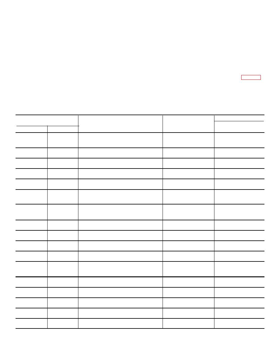
Table 7-15. Repair Standards (Right, Left Brake, Steer Clutch) |
|
||
| ||||||||||
|
|
 TM 9-2520-249-34& P
engage pins (6).
inside diameter downward, over oil baffle plate (7) and
j.
Install 12 springs (13) onto pins (15). Push
clutch disks (12 and 14). Rotate plate assembly (5) until
the through-holes in plate (7) aline with the 12 pins (15).
them through the holes in plate (7) and against disk (16).
h. Lower plate assembly (5), and guide spring
k. Install apply disk (2). flat side upward
guide pins (15) through the holes in plate (7). At the
(counterbores of smaller holes downward), onto the
same time, engage pins (6) with the cutouts in disks (12
assembly. Aline the smaller holes to engage all 12 pins
and 16). Also, two pins (8) in plate (7) must engage the
(15).
two slots in oil baffle plate (11). The ends of pins (6) in
l.
Using a press or C clamps, depress the
plate (7) should now rest on the flat surface on which the
brake apply disk until the pins project through the
entire assembly is sitting.
smaller holes in the disk. Install 12 snaprings (fig. 7-34).
i.
Install six external-tanged disks (4) and six
Release the pressure and remove the assembly from
internal-splined disks (3) alternately upon plate
the press.
assembly (5). Begin with an external-tanged disk (14).
The smaller cutouts in the tangs of disks (4) must
Table 7-15. Repair Standards (Right, Left Brake, Steer Clutch)
Wear limit
Reference
Size and fit
DS/GS
Foldout
Item
Point of measurement
of new parts
maintenance
7
2a
Thickness of disk................................ ..
0.2420 to 0.2540
0.2410
7
3a
Thickness of disk................................ ..
0.1580 to 0.1630
0.1480
7
4a
Thickness of disk................................ ..
0.1166 to 0.1226
7
1a
Thickness of baffle plate.......................
0.2400 to 0.2600
0.2200
7
12a
Thickness of disk................................ ..
0.1166 to 0.1226
*
7
13a
Free length of spring.............................
5.238
7
13a
Length under load ................................
3.99 at 27.13 to
3.99 at 25.63 lb
33.17 lb
7
14a
Thickness of disk................................ ..
0.1580 to 0.1630
0.1480
7
16a
Thickness of disk................................ ..
0.2420 to 0.2540
0.2410
8
113a
Thickness of disk................................ ..
0.242 to 0.254
0.241
8
117a
Thickness of disk................................ ..
0.5180 to 0.1630
0.1430
8
118a
Free length of spring.............................
5.238
*
8
118a
Length under load ................................
3.99 at 27.13 to
3.99 at 25.63 lb
33.17 lb
8
1119a
Thickness of disk................................ ..
0.1166 to 0.1226
8
120a
Thickness of baffle plate.......................
0.2400 to 0.2600
0.2200
8
127a
Thickness of disk................................ ..
0.1166 t o0.1226
*
8
128a
Thickness of disk................................ ..
0.1580 to 0.1630
0.1480
8
129a
Thickness of disk................................. .
0.242 to 0.254
0.241
*Replace when worn beyond new dimensions.
7-32
|
|
Privacy Statement - Press Release - Copyright Information. - Contact Us |