 |
|||
|
|
|||
|
|
|||
| ||||||||||
|
|
 TM 9-2520-249-34& P
necessary.
j.
Using an alinement tool of replacer (22,
steer plantar' carrier assembly (2) from brake hub (17)
as an assembly (fig. 7-31).
remove six pinions (7.3), 12 washers (7.1 and 7.6), 12
spacers (7.2 and 7.5) and 150 pinion rollers (7.4) from
the carrier.
NOTE
Pinions are a matched set and each pinion
and its component parts should be placed in
a separate container. If one pinion must be
replaced, it is necessary to replace the entire
set of six pinions.
k. Remove baffle (3) from carrier (4) only for
replacement.
l.
Remove ball bearing (12) from output shaft
assembly (8) only for replacement. Do not remove
retaining ring (10) except for replacement, as it is not
reusable.
7-100. Cleaning
Refer to paragraph 5-2 for cleaning recommendations.
7-101. Inspection and Repair
Refer to paragraph 5-3 for inspection and repair
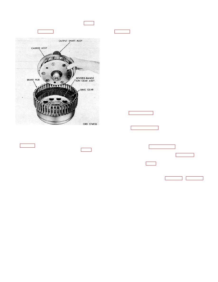
Figure 7-31. Removing for installing) steer planetary
recommendations.
carrier assembly.
c. Remove the steer planetary ring gear and
7-102. Repair Standards
the reverse-range sun gear assembly from the brake
hub (fig. 7-31).
repair standards.
steer planetary ring gear (13).
e. Remove reverse-range sun gear assembly
(15) from steer planetary ring gear (13).
f.
Do not disassemble reverse-range sun
a. If double-row ball bearing (12) was
gear assembly (15) If the gear or hub of assembly (15)
removed from output shaft assembly (8), install a new
is damaged, replace the entire assembly.
bearing. Using replacer (21, table 3-1), (fig. 7-32),
g. the lock tabs on oil collector (5) and
install the bearing onto the shaft. Press the bearing until
remove six bolts (6) the baffle on steer planetary carrier
it is firmly seated against the shoulder on the shaft.
(4).
h. Remove collector (5) from carrier (4).
i.
Remove six spindle lock pins (7.7) from
steer planetary carrier (4) by driving them toward the
inner diameter of the carrier and bending the pins if
7-28
|
|
Privacy Statement - Press Release - Copyright Information. - Contact Us |
