 |
|||
|
|
|||
|
|
|||
| ||||||||||
|
|
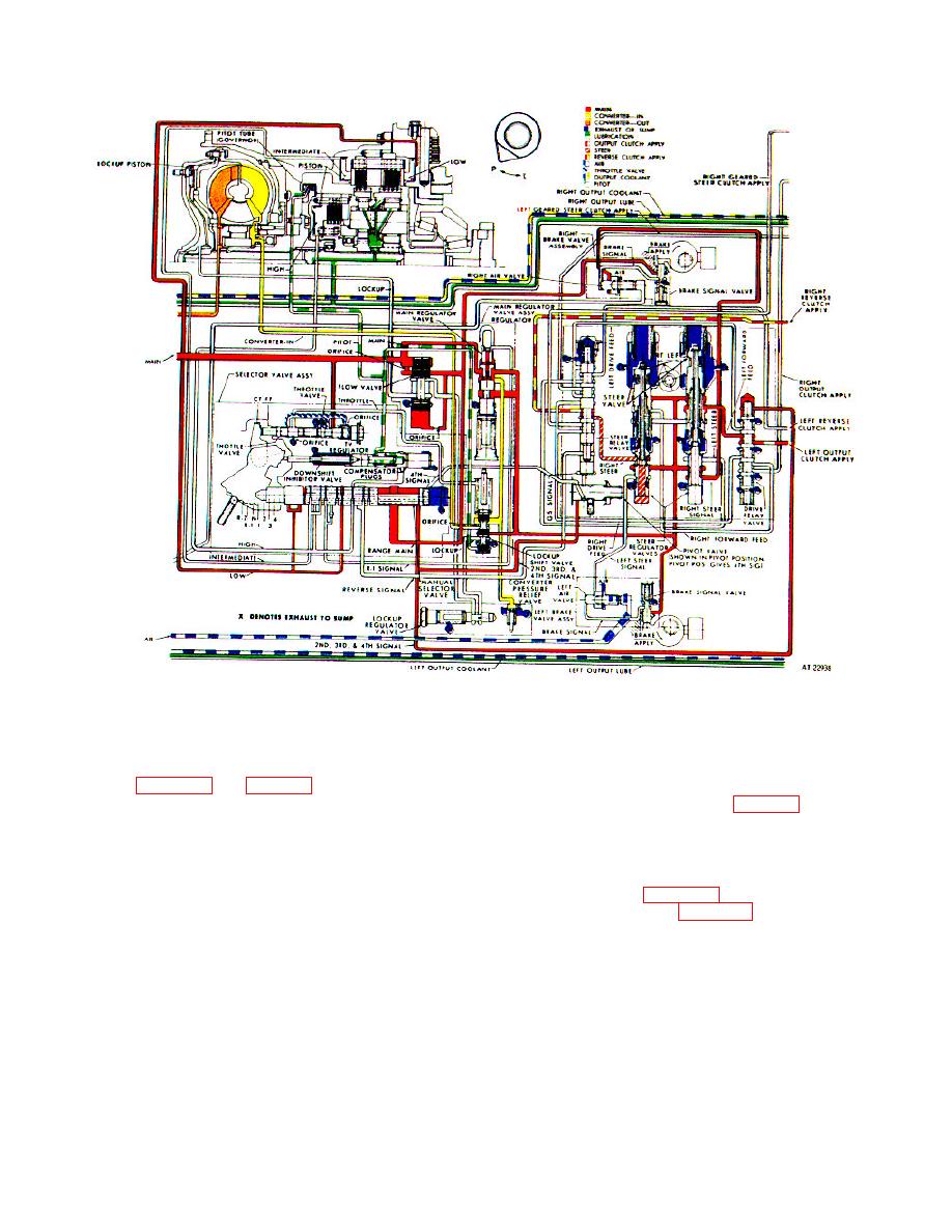 TM 9-2520-249-34&P
Figure 2-11. Hydraulic system, second gear pivot right steer operation-schematic view.
a. Operational Circuits. This driving condition
c.
Steer Relay Valve.
uses the same hydraulic circuits as second gear, normal
(1) The valve, in the downward position,
right steer (para 2-42, and fig. 2-10), except the vehicle
directs regulated steer pressure from the right steer
operator has selected pivot steer operation. In pivot
valve to the right reverse clutch (fig. 2-13), causing it to
steering, the vehicle pivots in every gear except fourth.
function as the steering element.
b. Pivot Valve (pivot water steer position). In
(2) When the steer relay valve is in the
upward position (fourth-gear signal), the reverse clutch
pivot position, the valve blocks the flow in the second-,
is exhausted and regulated steer pressure is directed to
third-, and fourth-signal circuit. Thus, during operation
the output clutch (fig. 2-13). Thus, pivot steer is
in second gear (also third) the steer relay valve is
prevented in fourth gear (para 2-38e).
downward.
2-26
|
|
Privacy Statement - Press Release - Copyright Information. - Contact Us |
