 |
|||
|
|
|||
|
Page Title:
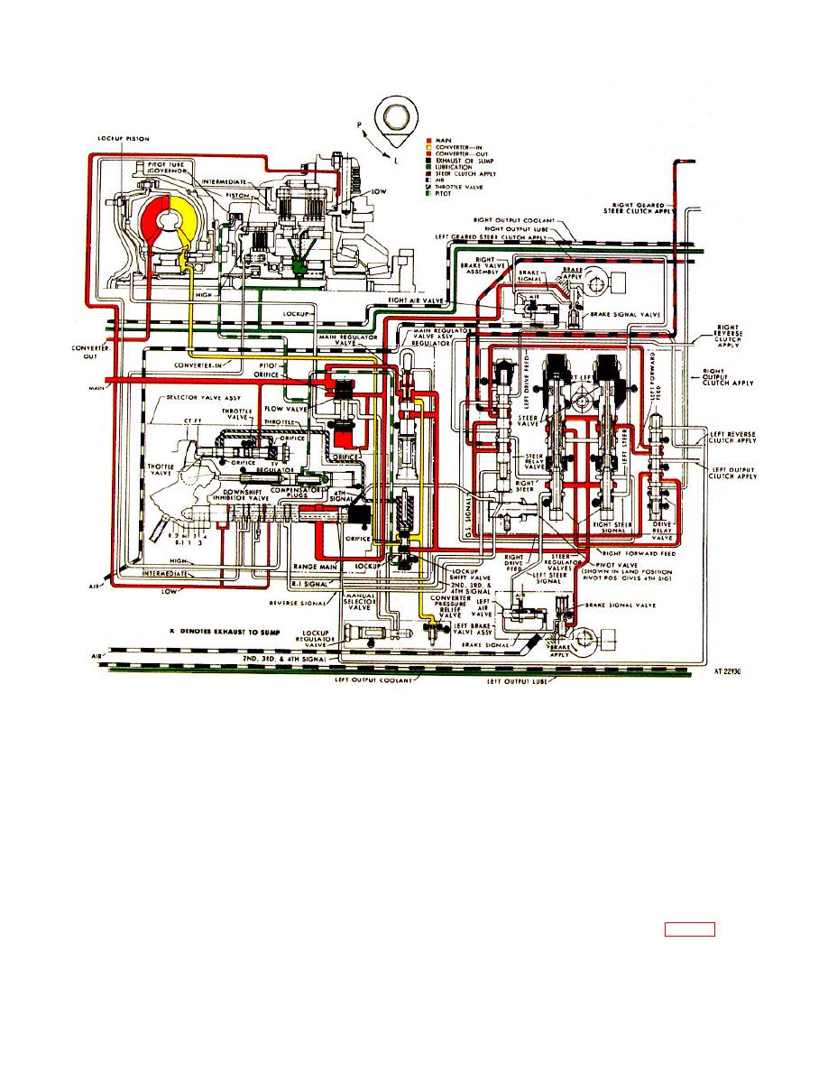
Figure 2-3. Hydraulic system, first gear, straight travel operation-schematic view. |
|
||
| ||||||||||
|
|
 TM 9-2520-249-34&P
Figure 2-3. Hydraulic system, first gear, straight travel operation-schematic view.
a. Operational Circuits. This driving condition
pressure oil is allowed to surround the stem of the
throttle valve and escape into the throttle circuit. This
uses the same circuitry as neutral except that the low-
circuit directs the TV pressure oil to the area above the
range clutch is engaged, and the output pump is
lockup shift valve where it assists the spring in opposing
actuated.
upward movement of the valve. Thus, at full throttle,
b. Manual Selector Valve.
The valve is
engagement of the lockup clutch is delayed. (TV
moved toward the right until the retaining ball rests in
pressure will also help to downshift the lockup shift
the first-gear detent. This allows a main-pressure port
valve at higher turbine speeds at heavy throttle.)
(upper passage) to index with a low-range clutch apply
d. Output-driven Pressure Pump. Forward
port. The low-range circuit becomes charged, thus the
vehicle travel causes the output-driven pump to rotate.
low-range clutch is engaged.
This pump assists the input-driven pump in supplying
c. Throttle Valve and Throttle Valve
main-pressure oil to the transmission (fig. 2-1).
Regulator.
The throttle is advanced to the full-throttle position. At
this setting, above three-quarter throttle, regulated
2-16
|
|
Privacy Statement - Press Release - Copyright Information. - Contact Us |
