 |
|||
|
|
|||
|
Page Title:
Cooler Bypass Valve and Converter-out Circuit |
|
||
| ||||||||||
|
|
 TM 9-2520-249-34&P
2-33. Lubrication Regulator Valve
2-32.
Cooler Bypass Valve and Converter-out
Oil from the oil cooler and cooler bypass valve is
Circuit
directed to the lubrication regulator valve. The regulator
The converter-out circuit directs oil returning from the
valve maintains the lubrication system pressure at 20
converter to the oil cooler and oil cooler bypass valve.
psi and also keeps the fluid-velocity governor cavity
(The oil cooler is not shown on the schematic because it
charged with oil.
When these requirements are
is a vehicle-furnished component.) When the differential
satisfied, the valve opens (20 psi) and allows the excess
pressure at the bypass valve exceeds 40 psi, the valve
to return to the transmission sump. Refer to paragraph
opens and allows some of the returning oil in the
converter-out line to flow into the lubrication circuit.
When the valve is closed (below 40 psi), all oil in the
circuit.
converterout circuit is directed to the oil cooler.
2-34.
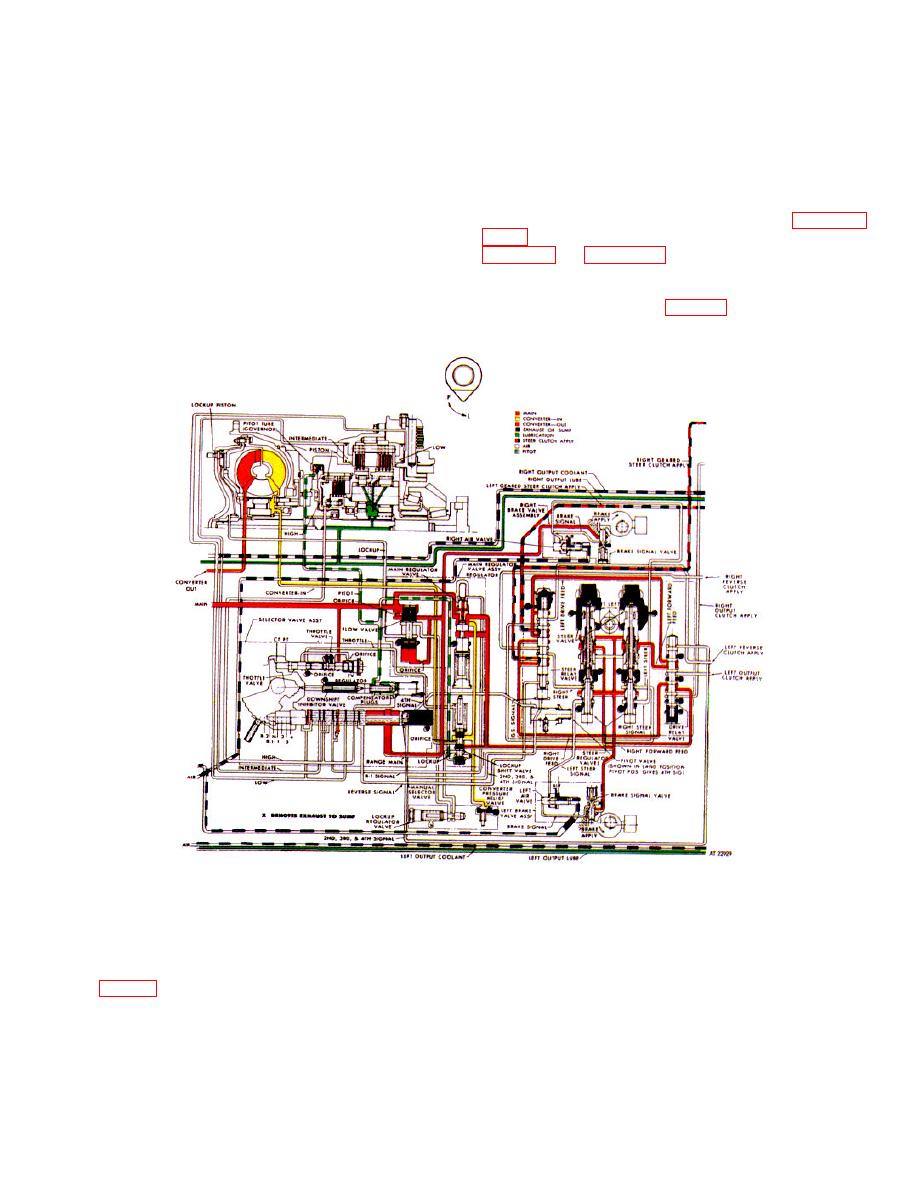
Figure 2-2. Hydraulic system, neutral operation--schematic view
a.
Main-Pressure Circuit (red).
pressure is also directed at all times to the steer
regulator valves, drive relay valve, and steer valves.
(1) Source and function. In neutral range,
(2) Throttle valve regulator.
Main
main pressure is supplied only by the input pressure
pressure is blocked at the valve bore by the throttle
pump (fig. 2-1). The oil is directed at all times to the
valve (TV) regulator. At closed throttle, the TV valve is
following valves: throttle valve regulator, flow valve,
held in place by spring compression against the throttle
manual selector valve, brake signal valves, main-
valve which in turn is positioned by the vehicle throttle.
pressure regulator valve, and lockup shift valve. Main
2-13
|
|
Privacy Statement - Press Release - Copyright Information. - Contact Us |
