 |
|||
|
|
|||
|
Page Title:
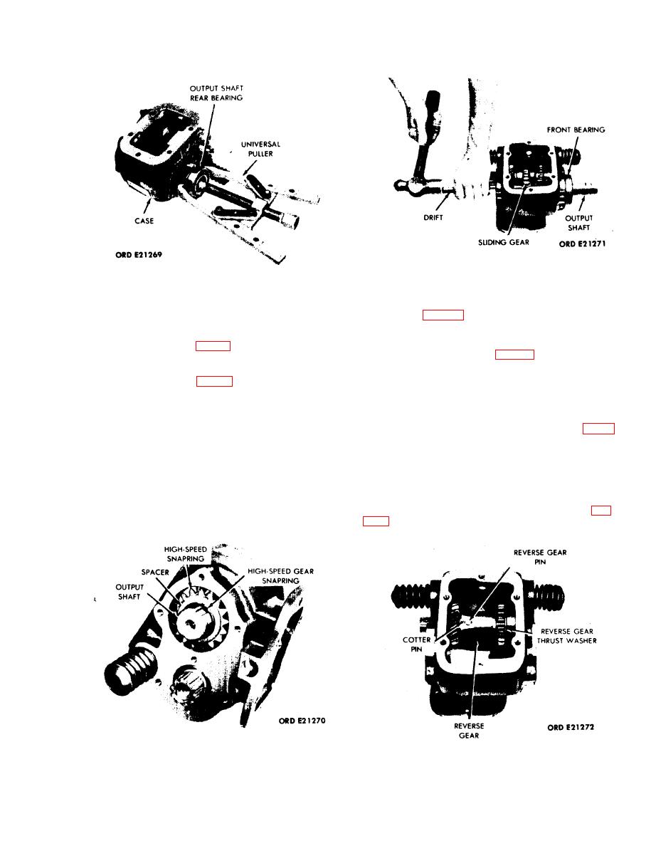
Figure 5-9. Removal of Output Shaft Rear Bearing. |
|
||
| ||||||||||
|
|
 TM 9-2520-246-34
Figure 5-11. Removal of Output Shaft, High-Speed
Figure 5-9. Removal of Output Shaft Rear Bearing.
Gear, and Front Bearing.
f. Output Shaft Rear Bearing.
spacer. (See fig. 5-10.)
(1) Push or tap output shaft rearward enough to
(2) Push or tap the output shaft and front
allow the rear bearing (fig. 5-9) to be removed.
bearing from the case. (See fig. 5-11.) Lift the sliding
gear out of the case.
(2) Using a universal puller remove the output
shaft rear bearing. (See fig. 5-9.)
h. Reverse Gear.
NOTE
(1) Remove the cotter pin securing the reverse
Use a wooden block or press to install rear
gear pin and remove the reverse gear pin. (See fig. 5-
bearing on the shaft and into the rear
12.)
bearing bore.
(2) Using a soft drift pin, tap the reverse
gearshaft and front roller bearing from the case.
g. Output Shaft and High-Speed Gear.
Remove the front roller bearing from the shaft.
(1) After the output shaft rear bearing is
(3) Remove the reverse gear thrust washers (fig.
removed, push the output shaft back into place.
Remove the snapring securing the high-speed gear and
Figure 5-10. Removal of Output Shaft High Speed Gear
Snapring and Spacer.
Figure 5-12. Removal of Reverse Gear.
5-5
|
|
Privacy Statement - Press Release - Copyright Information. - Contact Us |
