 |
|||
|
|
|||
|
Page Title:
Input Shaft Disassembly and Assembly. |
|
||
| ||||||||||
|
|
 TM 9-2520-246-34
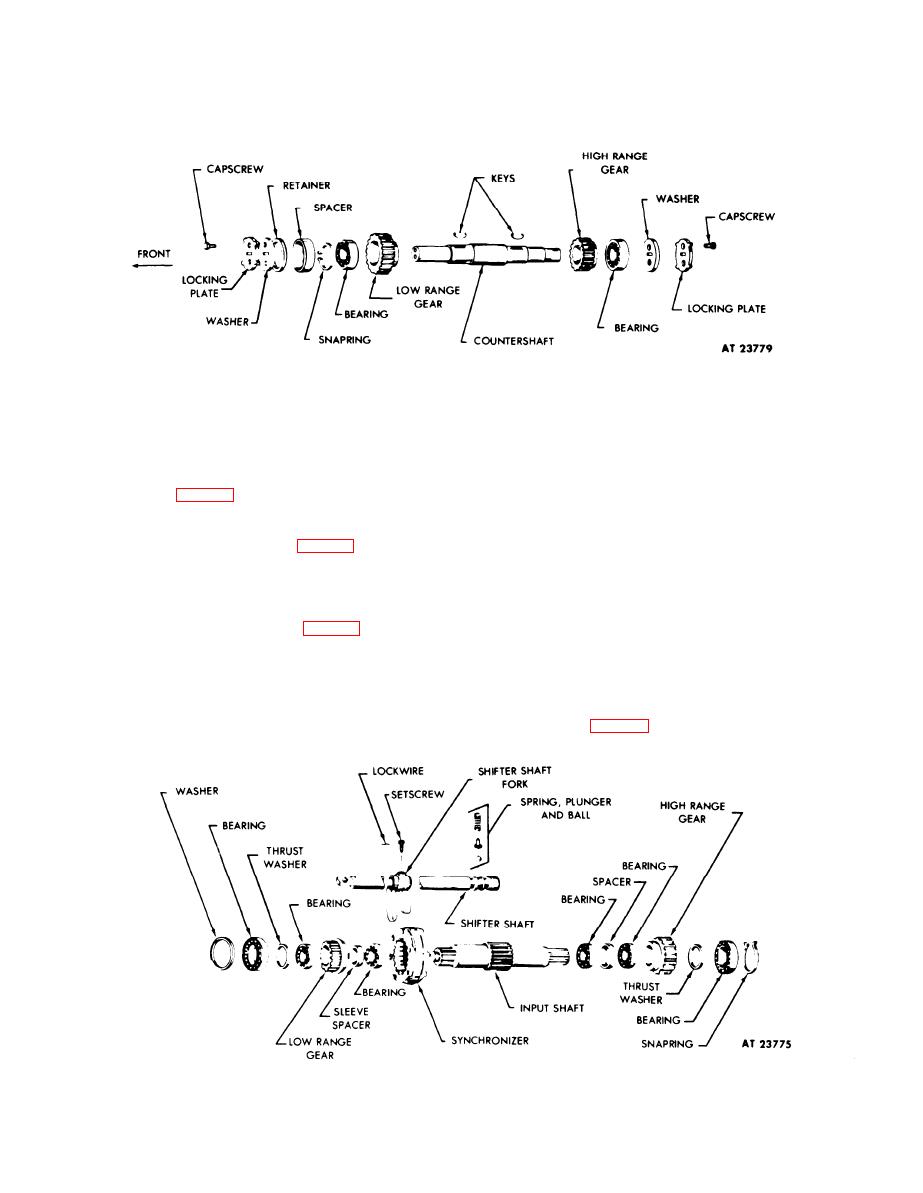
Figure 4-15. Countershaft Disassembly -- Exploded View.
(1) Using a suitable tool, bend the front and rear
NOTE
locking plate ears away from capscrews and remove
capscrews, locking plates, washers, and spacer (front
Visually inspect synchronizer assembly for
broken, nicked, or worn gear teeth. If any
only). (See fig. 4-15.)
of these conditions prevail, the
synchronizer must be replaced. For
(2) Place countershaft in a press with the
replacement, use synchronizer part number
countershaft high range gear (fig. 4-15) and rear
7346755.
bearing up. Place support bars beneath the high range
gear and rear bearing. Remove woodruff key.
NOTE
(3) Place the countershaft assembly in an arbor
press with the low range gear (fig. 4-15) and front
bearing up. Place support bars beneath the low range
gears onto the input shaft, coat all
installation surfaces with white lead
gear. Press shaft from countershaft low range gear
pigment, Fed Spec TT-W-261C.
and front bearing. Snapring and retainer is removed
with transfer case cover. Remove woodruff key.
(1) Remove shifter fork from synchronizer
assembly. (See fig. 4-16.)
c. Input Shaft Disassembly and Assembly.
,
Figure 4-16. Input Shaft Disassembly -- Exploded View.
4-8
|
|
Privacy Statement - Press Release - Copyright Information. - Contact Us |
