 |
|||
|
|
|||
|
|
|||
| ||||||||||
|
|
 TM 9-2520-246-34
shaft plug (fig. 4-11). Remove valve assembly (fig. 4-
n. Rear Output Shaft Rear Bearing Retainer.
12) from PTO flange.
NOTE
NOTE
During assembly, tighten the rear output
shaft rear bearing retainer capscrews to 60-
On assembly, install the valve with spring
77 lb-ft torque. Use shims to obtain 0.002-
toward inside of case.
to 0.005-inch end play. The shims are
provided as a set. The part number for the
4-6. Disassembly of Subassemblies.
set is 7521437. The part numbers and shim
sizes are:
a. Rear Output Shaft Disassembly and Assembly.
Thickness
Ordnance No.
NOTE
.003 .001
7521277
Before pressing the gear and bearings on
.005 .001
7521278
rear output shaft, coat shaft with white
.010 .001
7521279
lead pigment, Fed Spec TT-W-261C. When
assembling the rear output shaft assembly,
Remove the six capscrews and lockwashers
install the parts separately, so as not to
securing the rear output shaft rear bearing retainer to
damage front and rear bearings.
the transfer case. (See fig. 4-12.) Remove bearing
retainer and shims from the rear output shaft bearing
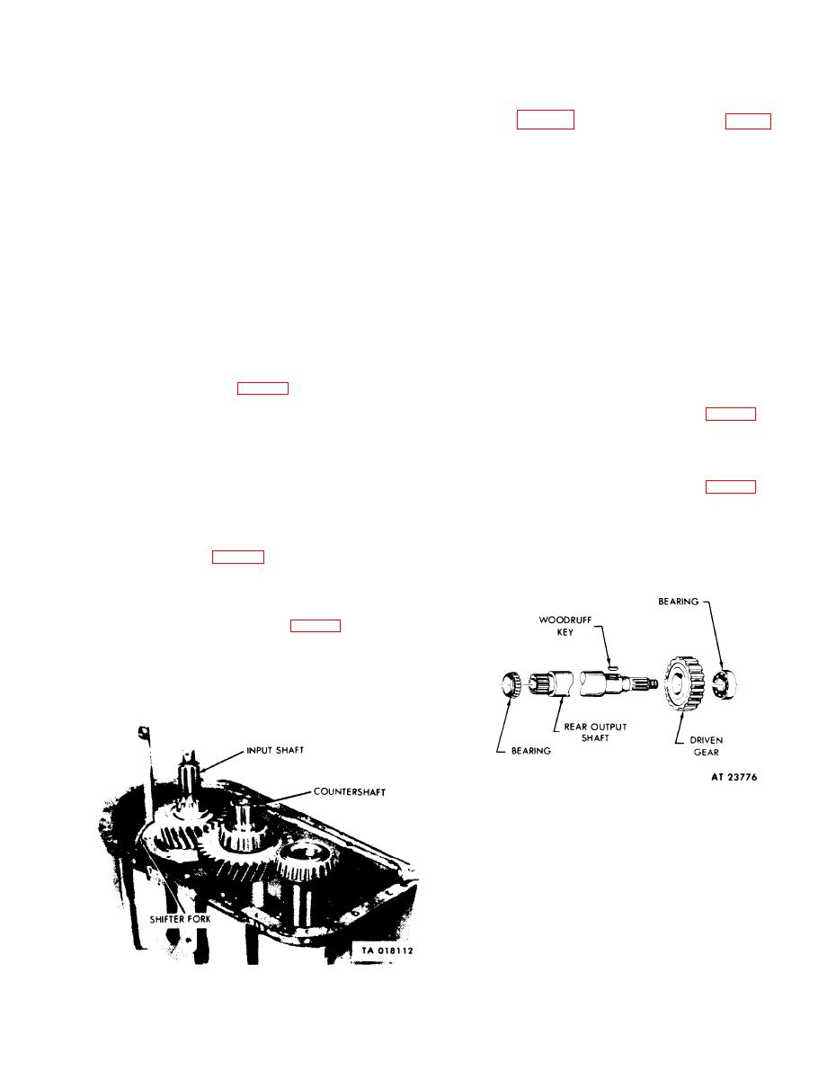
(1) Place rear output shaft assembly (fig. 4-14) in
retainer.
an arbor press with front tapered roller bearing cone
o. Input Shaft Rear Bearing Cover.
up. Place support bars beneath the cone. Press shaft
from cone.
NOTE
(2) Place rear output shaft assembly (fig. 4-14) in
During assembly, install a new gasket.
an arbor press with the rear output shaft driven gear
Tighten capscrews to 60-77 lb-ft torque.
up. Place support bars beneath the rear output shaft
Remove the six capscrews and lockwashers
driven gear and press shaft free of the gear. Removal
securing the input shaft rear bearing cover to the
of the rear output shaft driven gear in this manner
transfer case. (See fig. 4-12.) Remove rear bearing
will also push the rear output shaft rear bearing from
cover and gasket; discard the gasket.
the shaft. Remove the woodruff key from the shaft.
p. Shifter Fork, Input Shaft Assembly and
Countershaft Assembly. Using a soft pin and hammer,
drive the input shaft loose. (See fig. 4-13.) Then lift
the input shaft assembly, synchronizer assembly, fork
assembly, and countershaft assembly from the transfer
case.
q. Transfer Case Shifter Shaft Plug and Valve
Assembly. Using a suitable tool, remove the shifter
Figure 4-14. Rear Output Shaft Disassembly
-- Exploded View.
b. Countershaft Disassembly and Assembly.
NOTE
countershaft, coat shaft with white lead
pigment, Fed Spec TT-W-261C. When
assembling the countershaft assembly,
install parts separately so as not to damage
front and rear bearings. Discard old
capscrew locking plates and replace with
Figure 4-13. Shifter Fork, Input Shaft, and Countershaft.
new.
4-7
|
|
Privacy Statement - Press Release - Copyright Information. - Contact Us |
