 |
|||
|
|
|||
|
Page Title:
Figure 4-8. Front Output Shaft and Shifter Assembly |
|
||
| ||||||||||
|
|
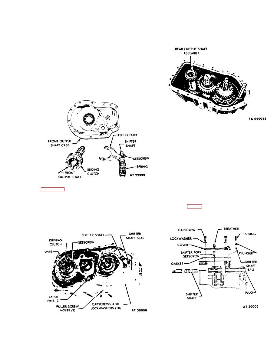 TM 9-2520-246-34
NOTE
Remove safety wire from clutch setscrew. Loosen
clutch setscrew and slide clutch from rear output
Follow procedures for cleaning and
shaft. (See fig. 4-9.)
inspection as outlined in Chapter 2, section
III of this manual.
NOTE
When assembling. tighten setscrew to 90-118
lb-ft torque. Remove front output shaft,
sliding clutch, shifter fork. shifter shaft,
shifter shaft spring, and retainer from front
output shaft case. (See fig. 4-8.) Remove
safety wire, loosen setscrew, and remove
shifter shaft from shifter fork.
Figure 4-10. Rear Output Shaft Assembly
j. Case Cover.
NOTE
Take care not to damage or lose taper pins
during removal; they are nonsupply items
which must be fabricated if lost or
damaged. Case and cover are a matched
set, mark both parts to retain identity for
assembly. Install taper pins and new gasket
Aline case cover with taper pins. and
tighten nut and capscrews evenly and
i. Front Output Clutch.
alternately. Tighten screws (indicated by Y
and W, fig. 4-5) to 60-77 lb-ft torque.
NOTE
Tighten remaining 12 screws to 67-87 lb-ft
torque.
When assembling, tighten setscrew to 45-57
lb-ft torque and install safety wire.
Figure 4-11. Top Cover and Shifter Shaft
Figure 4-9. Front Output Clutch Drive and Case Cover.
4-5
|
|
Privacy Statement - Press Release - Copyright Information. - Contact Us |
