 |
|||
|
|
|||
|
|
|||
| ||||||||||
|
|
 TM 9-2520-246-34
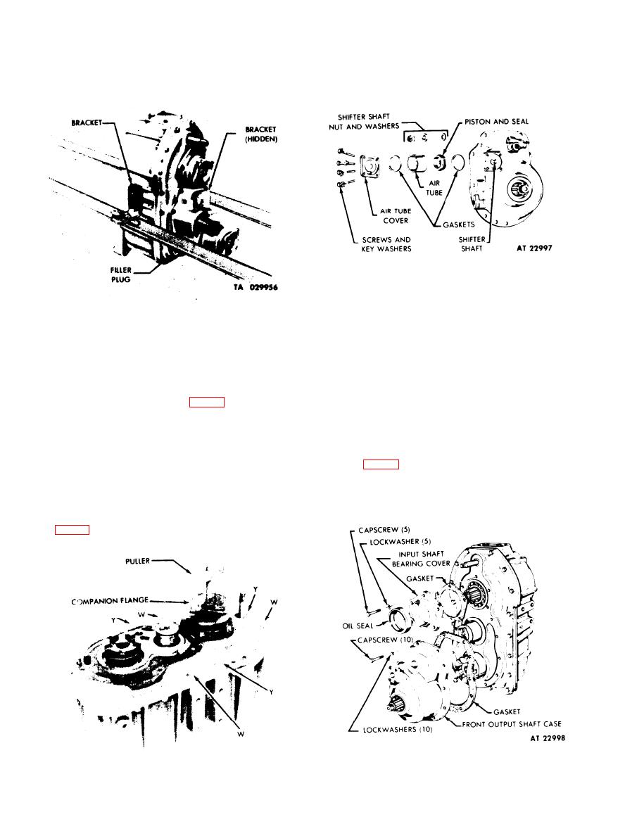
Figure 4-6. Air Cylinder Disassembly.
case. Pull the case assembly from the dowel pins on
Figure 4-4. Transfer Mounted on Stand.
the transfer case cover. Remove puller screws and
discard gasket.
Remove screws and key washers attaching air
cylinder assembly to drive output case. Lift and
g. Input Shaft Front Bearing Cover.
remove air tube cover. Slide air tube away from
cylinder piston. Remove nut and washers that connect
NOTE
air piston to shifter. Remove piston and rubber seal.
leaving clutch shaft in place. (See fig. 4-6.)
When assembling, install new gasket and
tighten capscrews to 60-77 lb-ft torque.
f . Front Output Shaft Case.
Remove the five capscrews and lockwashers from
NOTE
the input shaft bearing cover; remove cover and
gasket. (See fig. 4-7.) Using a suitable tool, remove the
When assembling, install new gasket and
oil seal from the cover. Remove outer thrust washer
tighten capscrews to 45-55 lb-ft torque.
from input shaft.
Remove 10 capscrews and lockwashers securing
h. Front Output Shaft.
the front output shaft case to the transfer case cover.
(See fig. 4-7.) Install puller screws into the two puller
screw holes in the flange of the front output shaft
Figure 4-7. Front Output Shift Case and Input
Shaft Bearing Cover.
Figure 4-5. Companion Flange Removal.
4-4
|
|
Privacy Statement - Press Release - Copyright Information. - Contact Us |
