 |
|||
|
|
|||
|
Page Title:
Section II. REPAIR (MODEL T-136-27) |
|
||
| ||||||||||
|
|
 TM 9-2520-246-34
Section Il. REPAIR (MODEL T-136-27)
d. Companion Flanges.
4-4. General.
NOTE
a. This section contains disassembly and assembly
procedures for transfer model T-136-27.
Apply a coating of white lead pigment. Fed
Spec TT-W-261C, to input shaft spline
b. Clean, inspect, and follow repair procedures as
before installing companion flange. Tighten
stated in Chapter 2. section III of this manual.
flange nut to 300-400 lb-ft torque.
c. Transfer disassembly is accomplished by the
(1) Using a puller (item 4, table 2-1), remove
logical step-by-step procedures in paragraphs 4-5 and
input shaft companion flange. (See fig. 4-5.)
4-6. Refer to paragraphs 4-7 and 4-8 for assembly
procedures.
NOTE
4-5. Disassembly of Transfer Into Subassemblies.
Apply a coating of white lead pigment, Fed
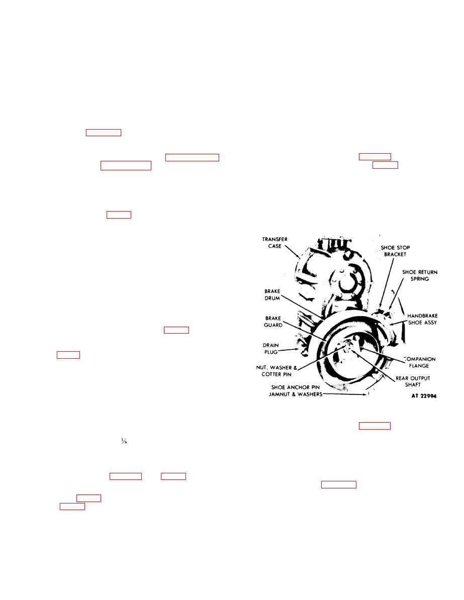
a. Handbrake Drum and Shoe Assembly. Remove
Spec TT-W-261C, to front output shaft
spline before installing companion flange.
the cotter pin (fig. 4-3) from the rear output shaft,
Tighten flange nut to 300-400, lb-ft torque.
front output shaft. and front input shaft. Engage input
shaft gears in HI or LOW position. Attach shop air
hose to transfer air cylinder. Apply air and engage
front output shaft with rear output shaft. Apply the
hand brake by hand, and remove the companion flange
nuts and washers from the three shafts. Shut off shop
air hose and remove the hose from the air cylinder.
Disconnect and remove the shoe return spring.
Remove the jamnut from the shoe anchor pin.
Unscrew the anchor pin from the rear output shaft
rear bearing retainer, do not lose washers. Slide the
hand brake shoe assembly from the brakedrum. Pull
the companion flange, braked rum, and brake guard
from the rear output shaft. (See fig. 4-5.) Remove the
two capscrews and lockwashers securing the shoe stop
bracket to the transfer case and remove bracket. (See
NOTE
Apply white lead pigment. Fed Spec TT-
W-261C, to the spline of the rear output
shaft before installing hand brake drum and
rear output shaft companion flange.
Tighten nut to 300-400 lb-ft torque. Place
Figure 4-3. Removal of Handbrake Assembly.
washers on anchor pin to space brakeshoe
so 1.16 inch of drum shows. Tighten pin
(2) Using a puller (item 4, table 2-1) remove front
until bind occurs when brake is applied.
output shaft companion flange.
and back-off
turn. Tighten locknut to
e. Air Cylinder.
153-196 lb-ft torque.
NOTE
b. Positioning of Transfer on Overhaul Stand.
Install transfer on overhaul stand using brackets
Reinstallation of air cylinder requires that
(items 1 and 2, table 2-1). (See fig. 4-4.)
cleaning, inspection and repair procedures
be followed in Chapter 2, section III of this
c. Draining. Remove transfer case magnetic drain
manual.
plug (fig. 4-3) and front output shaft cover filler plug
NOTE
To eliminate air leaks, install new gaskets
NOTE
and rubber seal. Make certain that the air
If chips are found, inspect in accordance
cylinder tube cover is tightened evenly
with repair and replacement standards.
when reinstalled. Tighten screws to 5-9 lb-ft
torque.
(Refer to section V.)
4-3
|
|
Privacy Statement - Press Release - Copyright Information. - Contact Us |
