 |
|||
|
|
|||
|
|
|||
| ||||||||||
|
|
 TM 9-2520-246-34
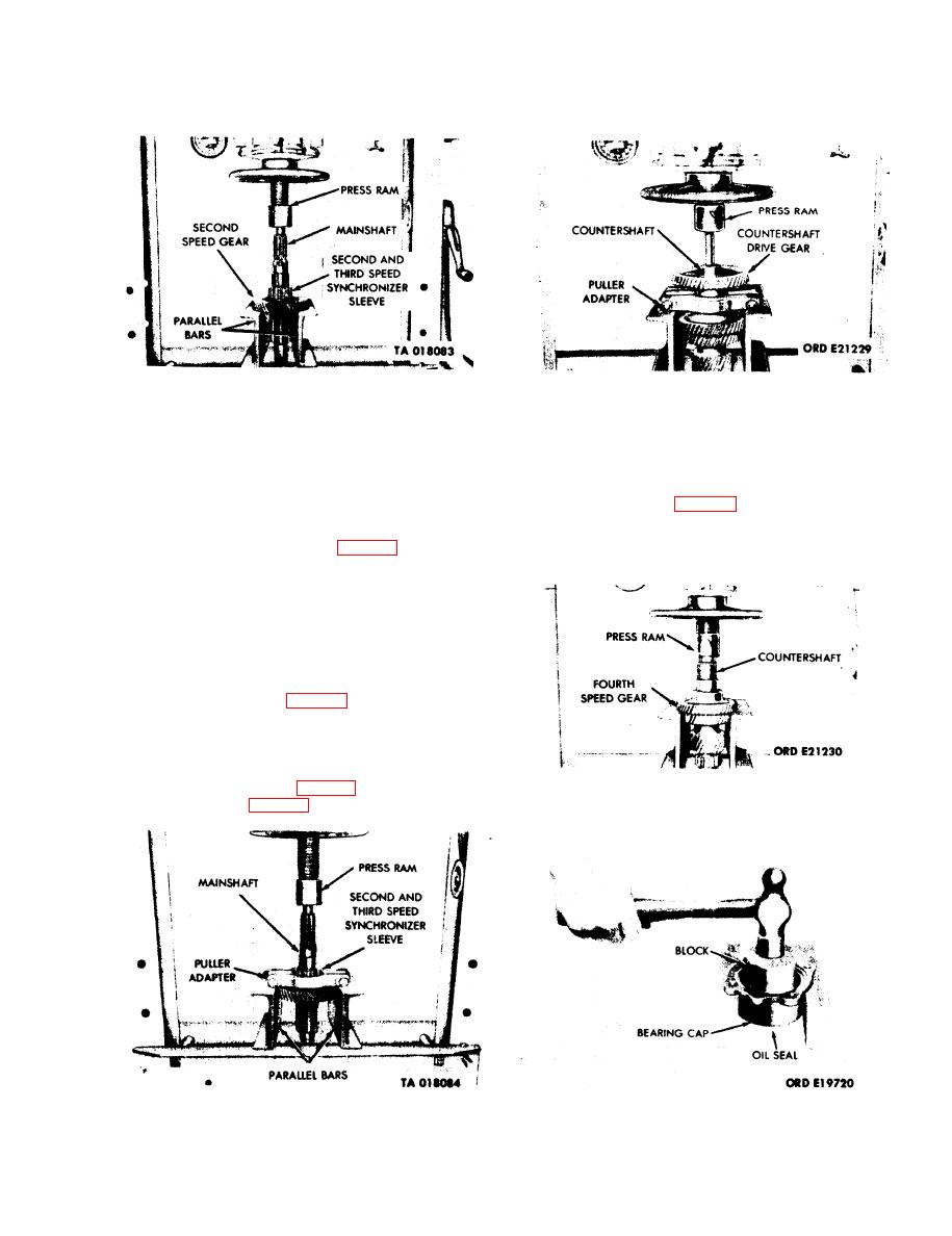
Figure 3-36. Removal Second-Speed Gear, Second-
Figure 3-38. Removal of Countershaft Drive Gear
and Third-Speed
(Fifth-Speed Gear).
Synchronizer and Synchronizer Sleeve.
3-10. Assembly of Subassemblies.
(4) Turn shifter shaft cover upside down, and
insert the springs and poppet balls into the shifter
a. Shifter Shaft Cover.
shaft cover holes. (See fig. 3-43) Depress the spring
and ball with a punch and slide the shaft through the
(1) Using a new oil seal, install the first and
shifter fork cover. Use the same procedure for
reverse shifter shaft oil seal. (See fig. 3-45.)
installing the remaining two poppet springs and balls.
NOTE
Soak felt seal in universal gear lubricant
(GO 90), MIL-L-2105, before assembly.
(2) Slide the lower shift lever into cover at
fulcrum pivot pins. Install lower shift lever, cup,
spring, and lockring. (See fig. 3-46.)
(3) Place the interlock plate into position and
install the springs and plate spring washers. Plate
spring washers are installed between the springs and
the shifter shaft cover. (See fig. 3-44.) Install the safety
Figure 3-39. Removal of Countershaft Fourth-
nuts and bolts. (See fig. 3-41.)
Speed Gear.
Figure 3-37. Removal of Second-Speed Gear, Second-
Figure 3-40. Removal of Mainshaft Rear Bearing
and Third-Speed Synchronizer and Synchronizer Sleeve.
Cap Oil Seal
3-17
|
|
Privacy Statement - Press Release - Copyright Information. - Contact Us |
