 |
|||
|
|
|||
|
|
|||
| ||||||||||
|
|
 TM 750-245-4
interface, or if proper heat balance has not been
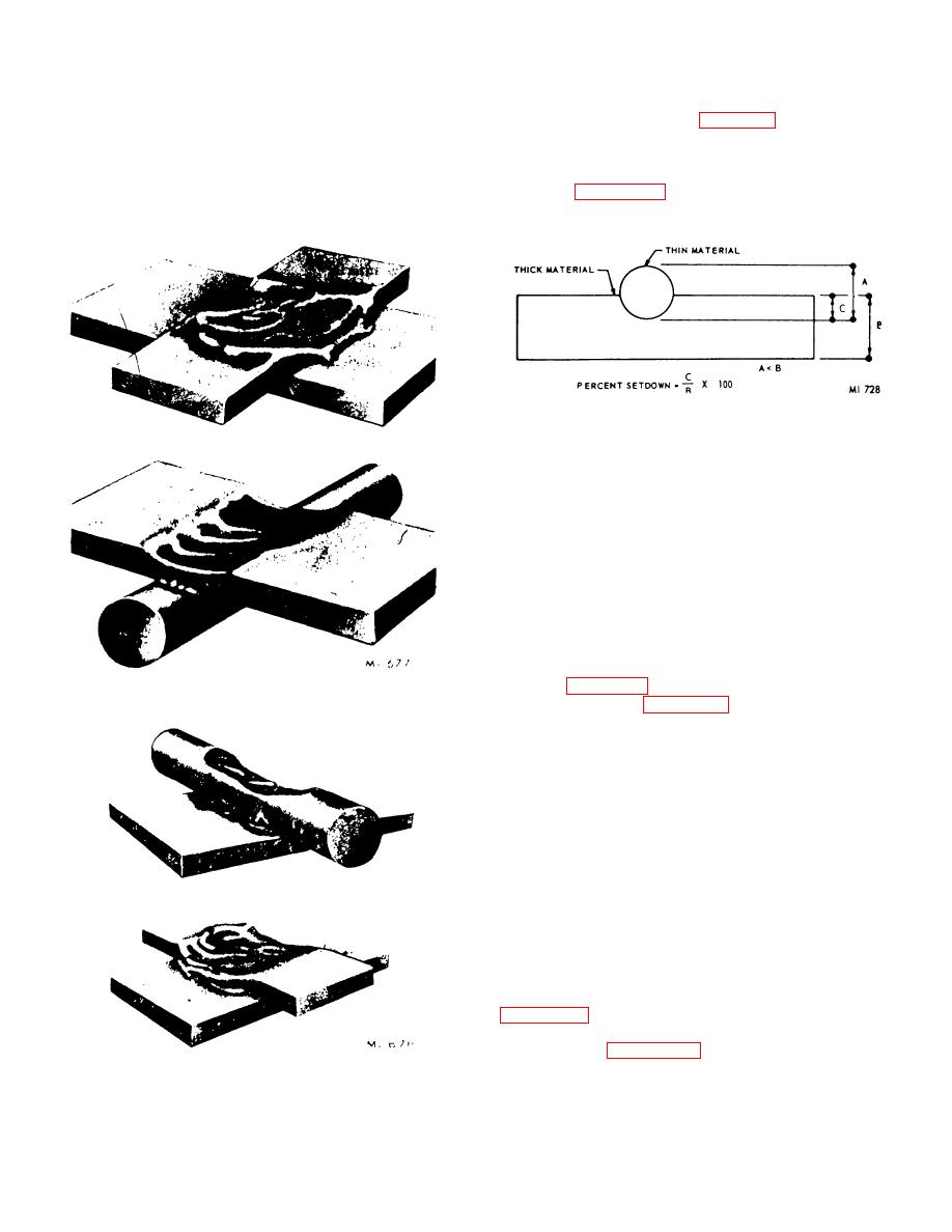
8-23. Excessive Setdown (Fig. 8-10)
attained, the contact area will melt. In certain cases, a
Setdown is the degree to which the thinner of the
small amount of surface fusion cannot be avoided.
materials being joined is physically forced into the
However, it is desirable to keep this to a minimum,
thicker material. It is expressed in percent, and is
preferably below 10 percent of the lead diameter.
shown in figure 8-10. Setdown should not exceed 50
percent.
Figure 8-10. Setdown.
8-24. Insufficient Weld
An insufficient weld is one in which fusion or forging
action has occurred, but not to the extent that minimum
weld strength requirements can be met. It is extremely
difficult to detect, and if this condition is suspected to
exist, a number of samples should be obtained from the
machine which produced the questionable welds and
pull tests made. In certain cases, as in round materials
welded to rectangular materials, it may be possible to
detect insufficient welds by observing the fillet at the
interface. The fillet should be evident at least along 75
percent of the interface. Normally, a defective weld will
exhibit two or more of the above conditions. For
example, figure 8-3 is an offset weld in which a weld
Figure 8-8. Pitted weld.
splatter is evident. Figure 8-5 exhibits cracks, excess
surface fusion, and excess metal bulging.
8-25. Destructive Inspection
a. Destructive inspection is made by either a pull-
test or metallurgical test. Pull-testing is time consuming
and expensive, and it destroys the product.
Nevertheless, it is the only method available at the
present time for obtaining quantitative data about the
parameters of a weld. Since this method is destructive,
it must be used only on a sampling basis.
b. The pull-test is commonly referred to as a
tensile test of the weld. The test consists basically of
pulling the weld apart by applying a tensile force of
opposite direction to each lead. Besides the tensile
force, there is also a shear force, and, in some
instances, a torsional force applied at the weld joint.
use by various companies for pull-testing welds.
Method A of figure 8-11 is the preferred pull-test
method. This method applies an additional stress to the
Figure 8-9. Excessive surface fusions.
joint.
8-7
|
|
Privacy Statement - Press Release - Copyright Information. - Contact Us |
