 |
|||
|
|
|||
|
|
|||
| ||||||||||
|
|
 TM 750-245-4
3-12. Wiring Harness Assemblies
Wiring harness assemblies are normally used internally
in chassis assemblies. They do not require weather
proofing protection and only in some cases require
potting of plug and jack assemblies. The inspector
should inspect for proper stripping, splices, lacing, wire
color, and proper wire size of replaced wiring.
a. Stripping.
Proper stripping is important to
accomplish a good solid and electrical connection. If
stripping is not properly done, arcing and burning may
result. The inspector will have to perform an in-process
inspection to insure that proper stripping is being
accomplished.
(1) Stripping is usually accomplished by a
mechanical stripping tool or a thermal stripper.
Generally, nonadjustable type mechanical strippers are
used because of the nonavailability of thermal-type
strippers. These mechanical strippers should never be
used on wire sizes 22 or smaller if there is a tendency to
stretch the wire. Also, care should be taken to prevent
nicking or cutting of the wire strands. Nicked or cut wire
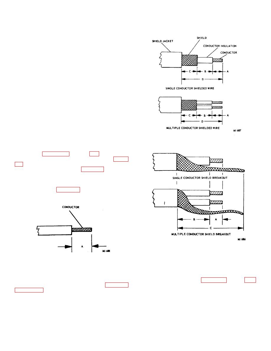
Figure 3-2. Stripping shielded conductor.
strands requires replacement of the wire if enough
length for restripping is not available.
(2) Figures 3-1 through 3-3 show proper
stripping, depending on the termination method. Figure
to the conductor plus 1/ 16 inch. Figure 3-2 illustrates a
ferrule or dead-end shield termination. Dimension C is
the length of the bowel to be crimped plus 1/16 inch.
For dead-ending, keep shield braid flush, within 1/8 inch
of the shield jacket. Figure 3-3 shows the pigtailing of
shields for grounding. Dimension C is determined by
the application.
Figure 3-3. Single and multiple conductor shield
breakout
Figure 3-1. Stripping single conductor.
c. Crimping. All crimping should be accomplished
b. Splicing.
The splicing of wiring harness
with properly qualified and calibrated tools.
The
assemblies is not recommended and should only be
inspector should inspect in-process to insure that the
accomplished as specified in the system documentation.
proper tools are being used. Figures 3-9 through 3-16
If splicing is to be accomplished tile following figures 3-4
are included to assist the inspector in determining that
the crimping is properly done.
determining that the splice is properly done.
d. Lacing. To prevent damage to insulation and
breaking of conductors caused by vibration and other
movements, the wires must be tied, together in
3-3
|
|
Privacy Statement - Press Release - Copyright Information. - Contact Us |
