 |
|||
|
|
|||
|
Page Title:
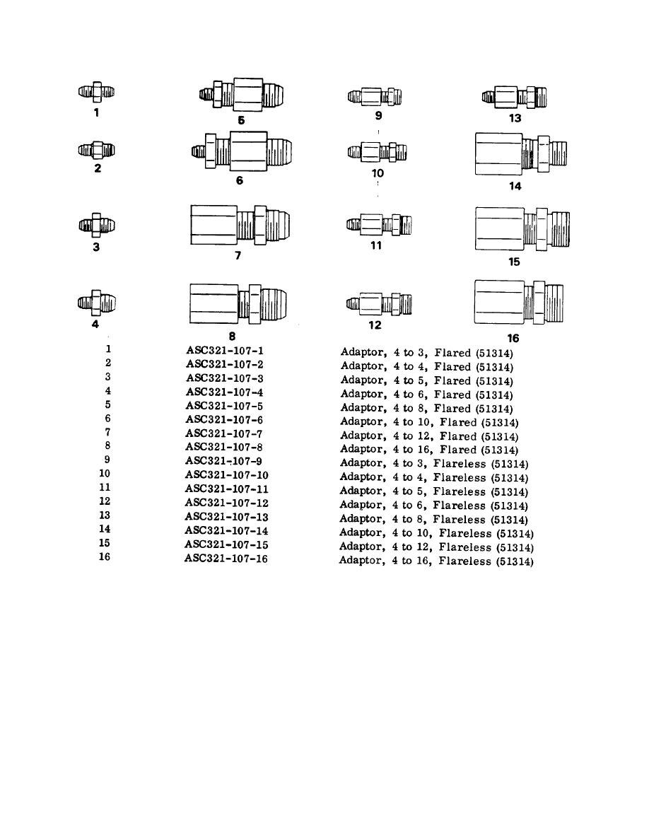
FIGURE 2-1. MODEL 321 HOSE TESTER COMPONENT RELATIONSHIP AND TEST CONNECTIONS (cont) |
|
||
| ||||||||||
|
|
 TM 55-4940-353-13&P
monitor the oil pressure gages (15 and 16). Slow
g. Open the oil control valve (13).
continuously falling pressure is evidence of a leak.
h. Detach the test hose (21) from the manifold
adaptor (19).
NOTE
When the air control valve (9) is initially
i. Drain oil in the test hose (21) by raising the
closed, the indicated pressure may drop as
manifold end above the oil return port.
much as 10 percent due to the expansion of
the hose.
j. Disconnect the test hose (21) from the oil return
adaptor (14).
f. After the desired test interval turn the pressure
regulator (3) fully counter clockwise.
2-4
|
|
Privacy Statement - Press Release - Copyright Information. - Contact Us |
