 |
|||
|
|
|||
|
Page Title:
SECTION II. PREPARING SHOP FOR OPERATION |
|
||
| ||||||||||
|
|
 TM 55-4920-440-13&P
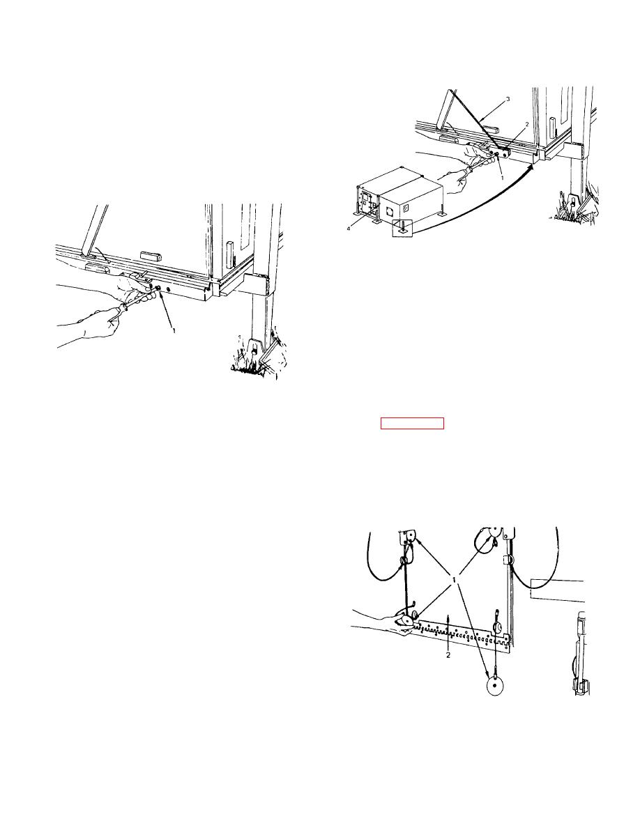
d. Counterbalance Cable Removal.
1. After shop erection is complete (AND
COUNTERBALANCE
CABLES
ARE SECURED),
remove three screws (1) from cable retainer block (2).
2. Let cable (3) and retainer block (2) hang
loose next to spring housing (4).
3. Reinstall retainer block screws (1) and
secure.
e. Shop is now ready for reconfiguration of
equipment to operational mode.
NOTE
All equipment or tools secured to
the floor or walls of the shelter
must be carefully tightened to
specific torque limits.
See
SECTION II. PREPARING SHOP FOR OPERATION
2-2. ECU Shelves, lowering procedures.
NOTE
The following procedures apply
only if the ECU are to be installed.
NOTE
(For shelter PN 136-0000-101)
One ECU opening is located in the
fold-out end wall and one ECU
opening is located in the fold-out
side wall.
(For shelter P/N 5-4-2828-1) Both
ECU openings are located in the
fold-out end walls.
One ECU
opening in each fold-out end wall.
a. Remove four plugs (1) on outside of each shelf
(2).
Change 1 2-3
|
|
Privacy Statement - Press Release - Copyright Information. - Contact Us |
