 |
|||
|
|
|||
|
|
|||
| ||||||||||
|
|
 TM 55-4920-426-13&P
3-156
MAGNETO REPLACE Continued
3-156
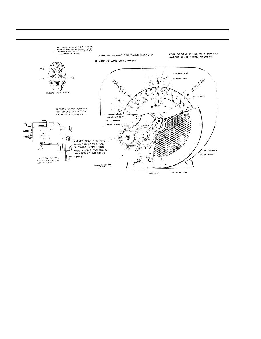
The No. 1 terminal is the upper right hand tower on the magneto cap. The terminals follow the pro-
f.
per firing order of 1-3-4-2 in a clockwise direction viewing the cap end. The leads from the magneto
should be connected to spark plugs of corresponding numbers.
When the magneto is properly timed the impluse coupling will snap when the `DC' and `X' marked
g.
vane of the flywheel, lines up with the mark on the flywheel which should indicate the centerline of
the No. 1 and 3 cylinders. This can be checked by turning crankshaft over slowly by hand. The im-
pulse will also snap every 180 of flywheel rotation thereafter.
h.
The proper spark advance is 23. To check timing with a neon light, the running spark advance is in-
dicated by a 1/8" diameter hole on the flywheel shroud, 23 before vertical centerline of the No. 1
and 3 cylinder. The end of the `X' marked vane should be whitened with chalk or paint for this
operation.
i.
The magneto rotates at crankshaft speed in clockwise direction when viewing driving gear end of
magneto. The magneto distributor rotor turns at half engine speed.
Install electrical wires on magneto stop switch.
j.
k.
Install No. 1 cylinder spark plug and lead.
l.
Install screw over flywheel air intake opening.
m
Install access panel.
END OF TASK
3-216
|
|
Privacy Statement - Press Release - Copyright Information. - Contact Us |
