 |
|||
|
|
|||
|
Page Title:
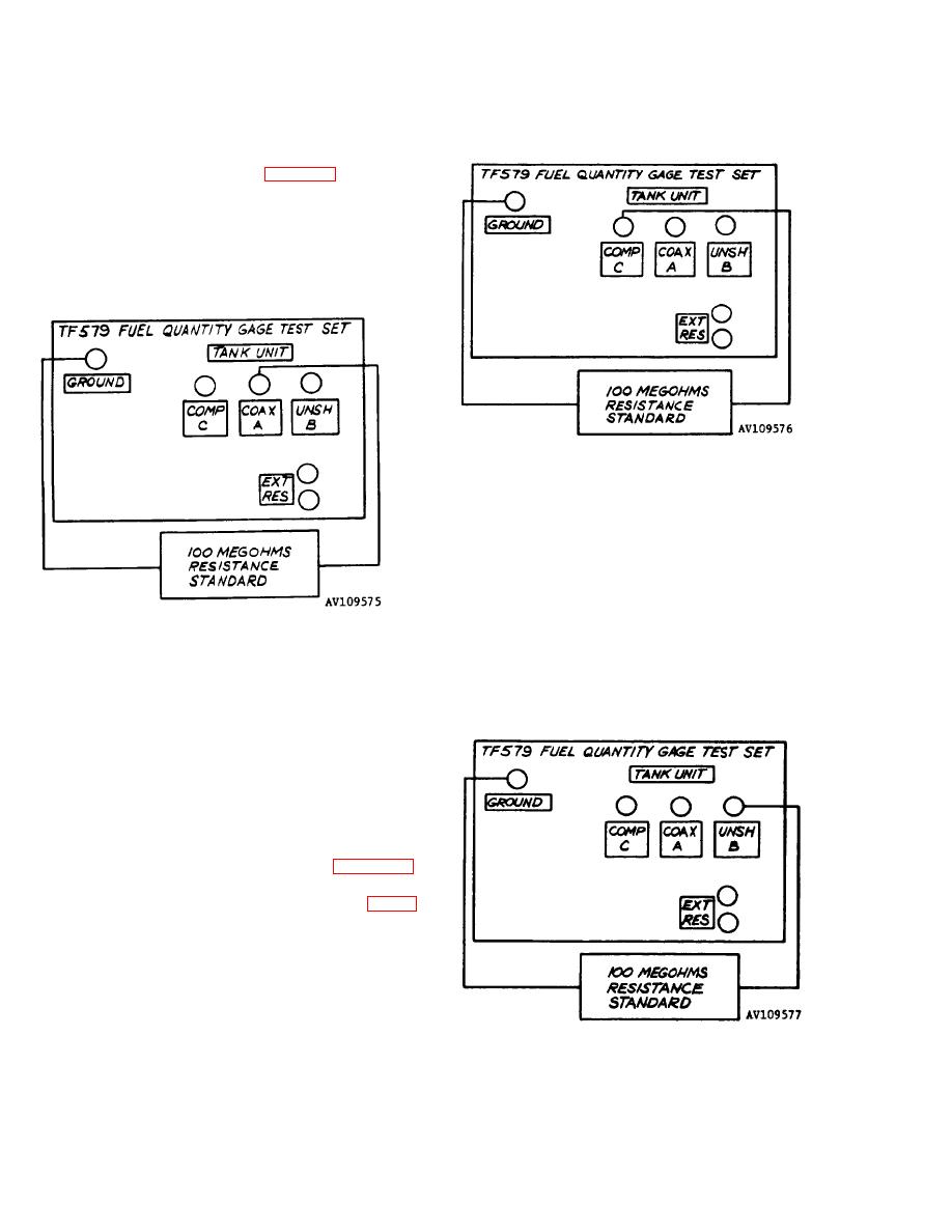
Figure 4-6. Setup for Checking Resistance Measuring Circuits Using TANK UNIT COAX A Connector and GROUND Terminal. |
|
||
| ||||||||||
|
|
 TM 55-4920-325-14&P
y. Set CAP-RES CHECK switch (13) to ME-
GOHMS A-GRD and repeat step w with 100 me-
gohm resistance standard connected across
T A N K UNIT COAX A connector (11) and
GROUND terminal (5) as shown in figure 4-6. Dis-
connect 100 megohm resistance standard.
Figure 4-7. Setup for Checking Resistance Mea-
suring Circuits Using TANK UNIT COMP C Con-
nector and GROUND Terminal.
Figure 4-6. Setup for Checking Resistance Mea-
suring Circuits Using TANK UNIT COAX A Con-
nector and GROUND Terminal.
z. Set CAP-RES CHECK switch (13) to ME-
GOHMS C-GRD B-GRD and repeat step w above,
with 100 megohm resistance standard connected
first across TANK UNIT COMP C connector (10)
and GROUND terminal (5) as shown in figure 4-7,
and then across TANK UNIT UNSH B connector
(12) and GROUND terminal (5) as shown in figure
4-8. Disconnect 100 megohm resistance standard.
aa. Set Power ON/OFF switch (2) to OFF and
disconnect standard resistance and all cables
from test set.
(part number 2688) as follows:
NOTE
Figure 4-8. Setup for Checking Resistance Mea-
suring Circuits Using TANK UNIT UNSH B Co
Use multimeter set to R X1 scale for all
nector and GROUND Terminal.
continuity checks.
4-4
|
|
Privacy Statement - Press Release - Copyright Information. - Contact Us |
