 |
|||
|
|
|||
|
Page Title:
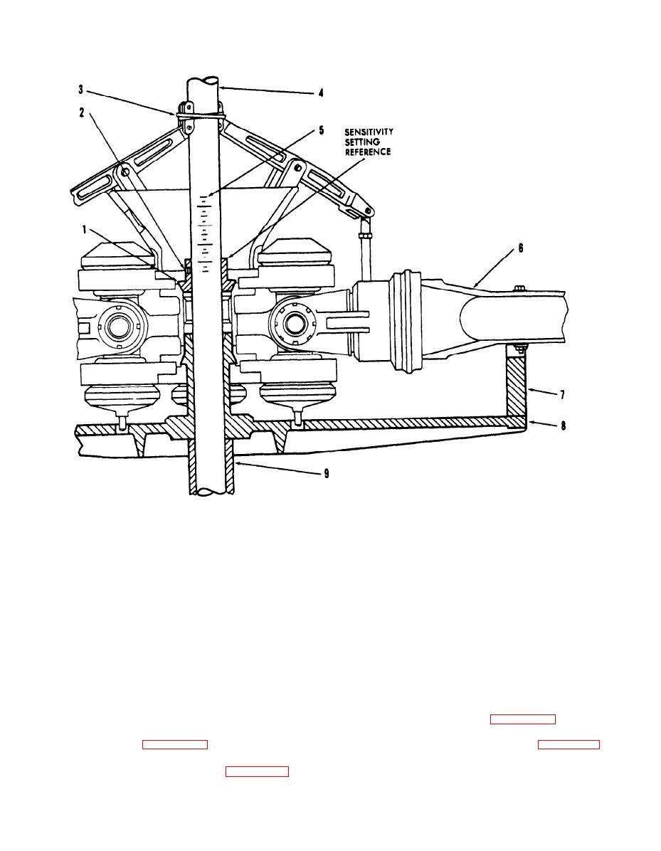
Figure 4-39. Balancer Installation - CH-37 Helicopter Tail Rotor Assembly. |
|
||
| ||||||||||
|
|
 TM 55-4920-201-14
1.
Cone (2206, 7A050 kit)
2.
Cone setscrew
3.
Elastic band
4.
Balancing arbor (2259.
7A050 kit)
5.
Arbor scale
6.
Tail rotor assembly
7.
Fixture support block
8.
Fixture assembly (2319,
7HEL052 kit)
9.
Spacer (2203, 7A050 kit)
Figure 4-39. Balancer Installation - CH-37 Helicopter Tail Rotor Assembly.
4-68. VERTOL HELICOPTERS.
b. Install sleeve (3, figure 4-40) as shown.
4-69. CH-47 Rotor Head Assembly Balance
Lock sleeve firmly in position with sleeve setscrew
Check. (See figure 4-40).
(4), using 1/8-inch hex wrench (8, figure 1-13).
a. Center plug (1), with bushing (2) installed,
c. Carefully lower rotor head assembly so that
on stand table assembly (1, figure 1-13).
splined hub of rotor assembly fits over outside
4-65
|
|
Privacy Statement - Press Release - Copyright Information. - Contact Us |
