 |
|||
|
|
|||
|
Page Title:
OH-58 Series Main Rotor Hub and Blade Assemblies Balance Check |
|
||
| ||||||||||
|
|
 TM 55-4920-201-14
Key
to figure 4-21:
1.
Stand table (7A050 kit)
2.
Fixture assembly (2532, 7HEL053 kit)
3.
Bar pair (11 sets) 2940 through 2950 (7HEL065 kit or AA4020-8508 kit)
4.
Post assembly (2) (2080, 7HEL065 kit or AA4920-8508 kit)
5.
Tail rotor hub and blade assembly
6.
Plate (2586, procure)
7.
Bushing (2533, 7HEL053 kit)
8.
Balancing arbor (2516, 7HEL053 kit)
9.
Arbor scale
10.
Bushing ret screw
Il.
Pilot bushing (2529, 7HEL053 kit)
12.
Lower fixture set screw
13.
Port thread
14.
Movable index action
15.
Index pin and set screw
16.
Tail rotor attaching nuts
17.
Tail rotor attaching bolts
VIEW A
VIEW B
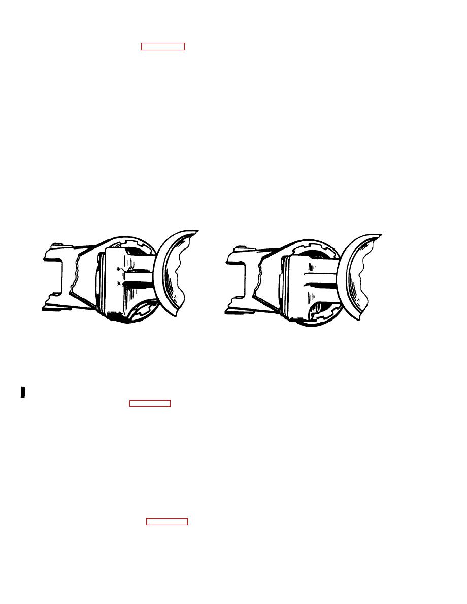
Figure 4-22. UH-1 and AH-1G Series
Tail Rotor Yoke Configurations
Identification for Proper Arbor Sensitivity Setting.
4-40. OH-58 Series Main Rotor Hub and Blade
lightly tighten ring nut (5) securing hub clamp
Assemblies Balance Check. (See figure 4-23).
section (6) of locks and adjust blades to ap-
proximately flat pitch with the arm positioing ring
a. Assemble the 7A050 kit work stand and
nuts (7). Remove rotor assembly from the
hoist support structure, substituting pert no. 2769
helicopter.
tube assembly in place of the part no. 2288 tube
assembly to provide the additional vertical height
e. Carefully install the rotor assembly on the
required for this application.
adapter (3) mounted on fixture (2), engaging
trunnion bore over pilot diameter of adapter and
b. Place the fixture (2) centrally on the work
seating firmly on cone surface.
stand (1).
f. Remove centrifugal tilt stop assembly from
c. Lower the adapter (3), large end down, over
rotors incorporating this mechanism.
the top extension of the fixture (2).
g. Observe oil level In grip and trunnion oil
d. Install pitch positioning locks (4) on the
reservoir sight glasses. Fill as required in ac-
rotor assembly between the pitch arms and hub
cordance with applicable helicopter maintenance
lower flange while the rotor is still mounted on the
manual.
helicopter mast. Refer to view A of figure 4-23, and
4-36
Change 6
|
|
Privacy Statement - Press Release - Copyright Information. - Contact Us |
