 |
|||
|
|
|||
|
Page Title:
Balancing Hartzell Flange-mounted Turbo. |
|
||
| ||||||||||
|
|
 TM 55-4920-201-14
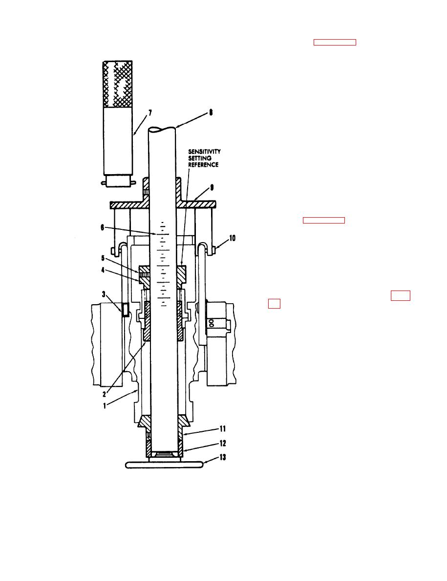
Key to figure 4-10:
1. Propeller assembly
2. Adapter (2453, 7A052 kit)
3 Wedge (2247, 7A052 kit)
4. Rear bushing (2210,
7A050 kit)
5. Bushing ret screw
6. Arbor scale
7. Installing tool (2452
7A052 kit)
8. Balancing arbor (2259,
7A050 kit)
9. Plate (2455, 7A052 kit)
10. Pitch arm link screw
11. Rear cone (2223, 7A050 kit)
12. Spacers (2203, 7A050 kit)
13. Hand wheel (2215, 7A050
kit)
4.22. Balancing Hartzell Flange-mounted Turbo.
propellers Reversing Type-Model HC-B3TN-3
Typical. (See figure 4-11.)
NOTE
Supplemental components not provided in
normal adapter kits are required to ac-
complish instructions included below.
These parts consist of: part no. 2769,
Tube; part no. 2792, Base Plate: part no.
2793, Stand Adapter Plate; and part no.
2816, Flange Adapter Assembly. See table
a. Remove piston and feathering spring
assembly, if installed, from the propeller. Assemble
TA050 work stand and hoist assembly using part
no. 2769 tube assembly in lieu of part no. 2288
tube (no. 4) provided in 7A050 kit.
b. Insure prop flange and pilot bore as well as
mating surfaces of the 2816 adapter (3) are
completely clean. Install pilot of adapter (3) in
prop flange bore. Check to insure adapter flange
seats squarely against prop flange. Retain with two
prop flange bolts, 180 apart.
c. Place 2793 plate (15) centrally on 7A050
stand table; place plate (14) centrally on top of
plate (15). Set propeller with flange adapter
downward, on top of part no. 2792 plate (14) and
visually align inside bore of adapter (3) with bore of
plate (14).
d. Install bushing (8), hub downward, on
arbor (9) so that top surface of bushing aligns with
13.inch position on arbor scale. Lock bushing
Figure 4-10. Typical Blancer Installation -
securely in this position with bushing set screw.
Single-cone, Splined Hub Assemblies with Shaft
e. Install arbor downward through prop hub,
Nuts Enclosed in Hub, Utilizing Pitch
Positioning Plate.
Change 1 4-17
|
|
Privacy Statement - Press Release - Copyright Information. - Contact Us |
