 |
|||
|
|
|||
|
Page Title:
Figure 4-2. Tiedown diagram for bucket in C-130 aircraft. |
|
||
| ||||||||||
|
|
 TM 55-3805-262-14
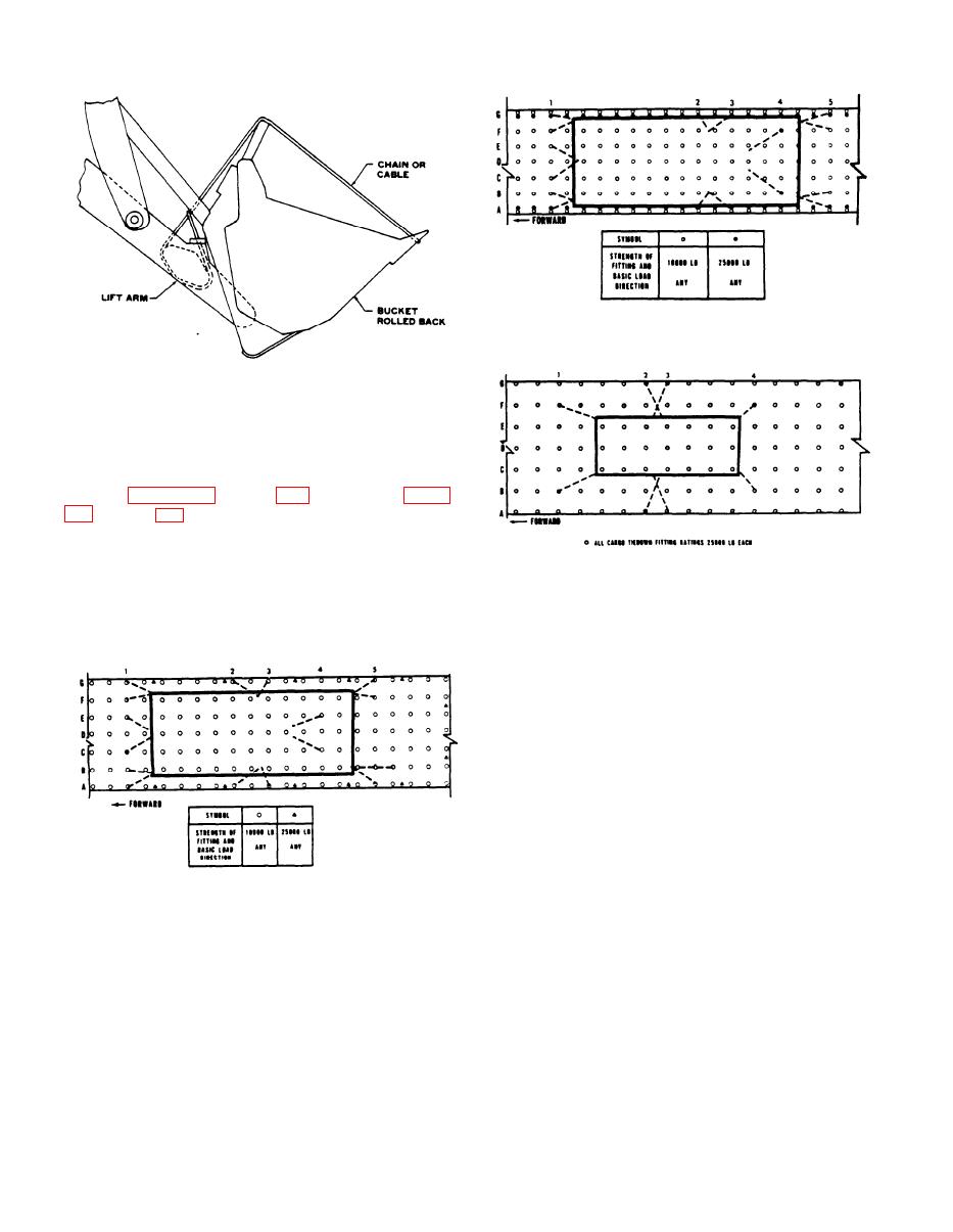
Figure 4-4. Tiedown diagram for MW24C scoop loader in C-141
aircraft.
Figure 4-2. Tiedown diagram for bucket in C-130 aircraft.
g. Restraint factors (g loads) for minimum ac-
ceptable conditions specified for crew and passenger
safety in the event of a controlled emergency landing
are specified in applicable aircraft TO. Tiedown
diagram figures 4-3 through 4-5 and tiedown tables
show representative tiedown patterns, and the tables
show the tiedown devices required (provided aboard
aircraft), tiedown points on the carrier, and cor-
Figure 4-5. Tiedown diagram for MW24C scoop loader in C-5
aircraft.
responding fitting on the aircraft floor to which the
devices are secured. Tiedowns will be applied as
directed by the aircraft loadmaster.
4-6. Transport by US Army Aircraft
The scoop loader exceeds size and weight limitations
for transport by US Army fixed or rotary wing
aircraft.
Figure 4-3. Tiedown diagram for MW24C scoop in C-130
aircraft.
4-2
|
|
Privacy Statement - Press Release - Copyright Information. - Contact Us |
|
|
Integrated Publishing, Inc. - A (SDVOSB) Service Disabled Veteran Owned Small Business
|

