 |
|||
|
|
|||
|
Page Title:
Table 7-1. Bill of Materials for Blocking and Tiedo wn of Truck Tractor, M746 and M911, on CONUS General-Purpose Flatcar (Fig... |
|
||
| ||||||||||
|
|
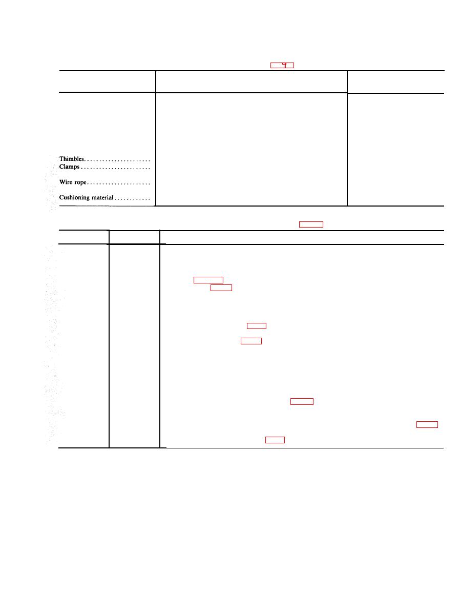 TM 55-2320-258-14
Approximate
Item
Description
quantity
Lumber . . . . . . . . . . . . . . . . . . . . . . .
Douglas-fir or comparable, straight-grain, free from material de-
fects; Fed Spec MM-L-751H: 2- x 4-in. . . . . . . . . . . . . . . . . . . . .
108 linear ft
2- x 6-in. . . . . . . . . . . . . . . . . . . . .
77 linear ft
12 linear ft
6- x 8-in. . . . . . . . . . . . . . . . . . . . .
Nails . . . . . . . . . . . . . . . . . . . . . . . . .
Common, steel; flathead, bright or cement-coated; Fed Spec
FF-N-105B:
12d . . . . . . . . . . . . . . . . . . . . . . . . . . .
60
AM.. . . . . . . . . . . . . . . . . . . . . . . . . .
224
God . . . . . . . . . . . . . . . . . . . . . . . . . . .
56
Standard, open-type 5/8-in . . . . . . . . . . . . . . . . . . . . . . . . . . . . . . . . . . . . .
16
Wire rope, U-bolt clips, saddled, single-grip, steel, Crosby heavy-
duty, or equal; Fed Spec FF-C-450D: 5/8-in . . . . . . . . . . . . . . . . . . .
48
6 x 19, IWRC; improved plow steel; preformed, regular-lay; table
X, Fed Spec RR-W-410C:5/8-in. . . . . . . . . . . . . . . . . . . . . . . . . . . . .
120 ft
Waterproof paper, burlap, or other suitable material . . . . . . . . . . . .
as required
Tractor, M746, on CONUS General-Purpose Flatcar (Figs 7-1 and 7-3)
Item
No. required
Application
A
Brake wheel clearance. Minimum clearance required in 6 in. above, in back of, and on both sides of,
and 4 in. underneath wheel, 12-inch minimum clearance from end of car to load, extending from
center of brake wheel to side of car and 6 ft above car floor (fig 7-l).
B
Blocks. Each to consist of one piece of 2- x 6- x 25-in. lumber. Locate one block against wheels as
8
shown in figure 7-1, and nail to car floor with five 20d nails.
c
8
detail 1. Locate one block on top of each item B with 45-degree side against tire. Nail heel of block
to item B with three 40d nails. Toenail sides of block to car floor through item B with two 40d nails
on each side. (Pattern 16)
1 ea item E
Cushioning material. Locate bottom portion under item E, and between tire anditem E seas to extend
D
2in. above item E (detai12, fig 7-3).
4
E
Side block. Each to consist of one piece of 2- x 6- x 108-in. lumber and three pieces of 2- x 4- x
108-in. lumber (detai12, fig. 7-3). Nai12- x 6- x 108-in. piece to edge ofbottom2- x 4- x 108-in.
piece with fifteen 12d nails. Place against inside of tires and cushioning material and nail to car floor
through 2- x 4- x 108-in. piece with twelve 20d nails. Nail other two 2- x 4- x 108-in. pieces to
one below in the same manner. (Pattern 89)
Brace. Each to consist of one piece of 2- x 6- x length to-suit (approximately 72 in.) lumber. Locate
F
4
one under each axle between items E Nail to car floor with ten 20d nails.
Wire rope. Each to consist of one piece 5/8-in. 6x19, IWRC wire rope, length as required
G
8
(approximately 20 ft). Form a complete loop between tiedown shackle and appropriate stake pocket
at a maximum angle of 45 degrees (detail 3. fig. 7-3). Wire rope ends should overlay approximately
24 in.
H
16
Thimbles. Place one under wire rope at each place where rope passes over bottom edge of stake pocket
Clamps. Place four on each item H at overlap area. Space clamps 31/2 in. apart with a minimum of 6
48
J
in. from endsof wire rope (detail 3, fig 7-3). Place one on each item J as indicated above.
GENERAL INSTRUCTIONS
1. Set handbrakes, and block and wire levers in place.
2. Place and wire-tie gearshift levers in the neutral position.
3. See General Rules 1, 2, 3, 4, 5, 14, 15, 19A, and 19B, Section I of the Rules Governing the Loading of Commodities on Open-Top Cars
and Trailers published by the Association of American Railroads for further details.
4. Tension wire rope with inapplicable sized come-along mechanical hoist or equal tensioning device.
Change 1
|
|
Privacy Statement - Press Release - Copyright Information. - Contact Us |
