 |
|||
|
|
|||
|
Page Title:
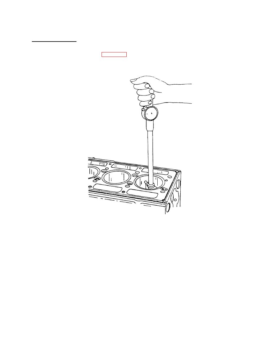
Figure 4-40. Checking Bore of Cylinder Liner Using Tool J5347-01 |
|
||
| ||||||||||
|
|
 TM 55-1930-208-24
4-12. CYLINDER LINERS - Continued.
c. Inspection - Continued.
(5) Install liner in the proper bore of the cylinder block. Measure inside diameter of the liner at the various points.
Use cylinder bore gage J5347-01 (figure 4-40), which has a dial indicator calibrated in .0001 inch increments.
Set cylinder bore gage on zero in master ring gage J5580-1. Also check liner for taper and out-of-round. It is not
necessary to measure the inside diameter or taper of a new liner.
Figure 4-40 .
Checking Bore of Cylinder Liner Using Tool J5347-01 .
NOTE
Dial bore gage master setting fixture J23059-01 may be used in place of the master ring gage.
(6) The piston-liner clearance must be within the specified limits. Also, the taper must not exceed .002 inch and the
out-of-round must not exceed .0025 inch on a used liner. If the out-of-round exceeds .0025 inch, rotate the liner
900 in the block bore and recheck.
(7) New service liners, standard and oversize, have an inside diameter of 4.2495 inch to 4.2511 inch (long port liner)
or 4.2495 inch to 4.2516 inch (short port liner).
4-50
|
|
Privacy Statement - Press Release - Copyright Information. - Contact Us |
