 |
|||
|
|
|||
|
Page Title:
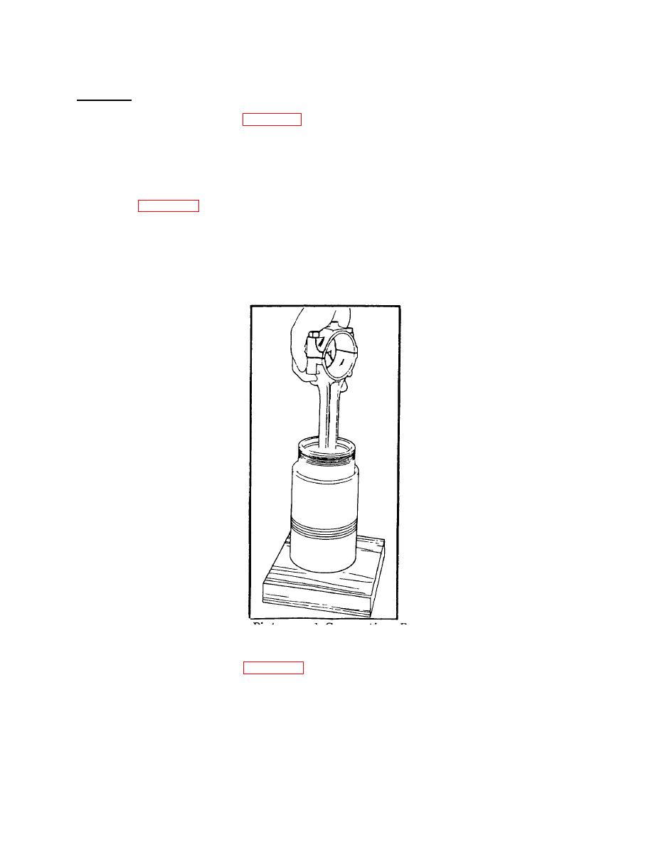
Figure 4-36. Installing Piston and Connecting Rod Assembly in Ring Co mpressor and Cylinder Liner |
|
||
| ||||||||||
|
|
 TM 55-1930-208-24
4-11. PISTONS AND CONNECTING RODS- Continued.
g. Installation.
(1) Apply clean engine oil (item 8, Appendix C) to the piston, rings, and inside of ring compressor.
NOTE
Inspect ring compressor for nicks or burrs, especially at the non-tapered inside diameter end. Nicks or
burrs on the inside diameter of the compressor will result in damage to piston rings.
(2) Refer to figure 4-36. Place piston ring compressor on a wood block, with tapered end of ring compressor
facing up.
(3) Position (stagger) the piston ring gaps properly on the piston.
Make sure ends of the oil control ring
expanders are not overlapped.
(4) Start top of the piston straight into ring compressor. Then push piston down until it contacts the wood block.
Figure 4-36 .
Installing Piston and Connecting Rod Assembly in Ring Co mpressor and Cylinder Liner .
(5) Remove connecting rod cap (2, figure 4-22).
(6) Place ring compressor, piston, and connecting rod assembly on liner so the numbers on the rod and cap are
aligned with the matchmark on the liner.
4-44
|
|
Privacy Statement - Press Release - Copyright Information. - Contact Us |
