 |
|||
|
|
|||
|
Page Title:
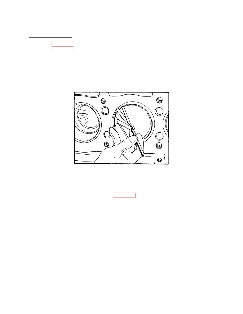
Figure 4-32. Measuring Piston Ring Gap |
|
||
| ||||||||||
|
|
 TM 55-1930-208-24
4-11. PISTONS AND CONNECTING RODS - Continued.
f. Reassembly - Continued.
(16) Refer to figure 4-32. If the gap on a compression ring is insufficient, it may be increased by filing or stoning
the ends of the ring. File or stone both ends of the ring so the cutting action is from the outer surface to the inner
surface. The ends of the ring must remain square and the chamfer on the outer edge must be approximately
.015 inch.
(17) Each piston is fitted with a fire ring, two compression rings, and two oil control rings.
(18) The top (fire) ring and the upper compression ring (second groove) areprestressed. Both are identified by
a small indentation mark on the top side.
Figure 4-32 .
Measuring Piston Ring Gap .
NOTE
The current piston crowns (18.7:1 and 17:1 compression ratio) have a tapered fire ring groove. To
conform with this change, a tapered fire ring (figure 4-33) must be used. The former piston crown (17:1
compression ratio) had a rectangular fire ring groove. Only pistons with the tapered fire ring groove are
available for service.
4-40
|
|
Privacy Statement - Press Release - Copyright Information. - Contact Us |
