 |
|||
|
|
|||
|
Page Title:
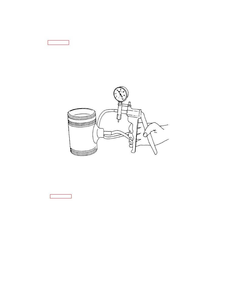
Figure 4-30. Checking Piston Pin Retainer for Proper Sealing Using Tool J23987-01 |
|
||
| ||||||||||
|
|
 TM 55-1930-208-24
4-11. PISTONS AND CONNECTING RODS - Continued.
f. Reassembly - Continued.
(9) Refer to figure 4-30 and check each retainer for proper seating with leak detector J23987-01. Place the
suction cup over the retainer and hand operate the lever to pull a vacuum of ten inches on the gage.
(10) Measure piston skirt diameter lengthwise and crosswise of piston pin bore. Measurements should be taken
at room temperature (70 or 21 ).
F
C
(11) The piston-to-liner clearance, with new parts, will vary with the particular piston and cylinder liner. A
maximum clearance of .012 inch is allowable with used parts.
Figure 4-30 .
Checking Piston Pin Retainer for Proper Sealing Using Tool J23987-01 .
(12) With cylinder liner installed in cylinder block, hold piston skirt upside down in the liner and check clearance
in four places 90apart.
(13) Refer to figure 4-31 and use feeler gage set J5438-01 to check the clearance. The spring scale attached to
the proper feeler gage, is used to measure the force in pounds required to withdraw feeler gage.
4-38
|
|
Privacy Statement - Press Release - Copyright Information. - Contact Us |
