 |
|||
|
|
|||
|
Page Title:
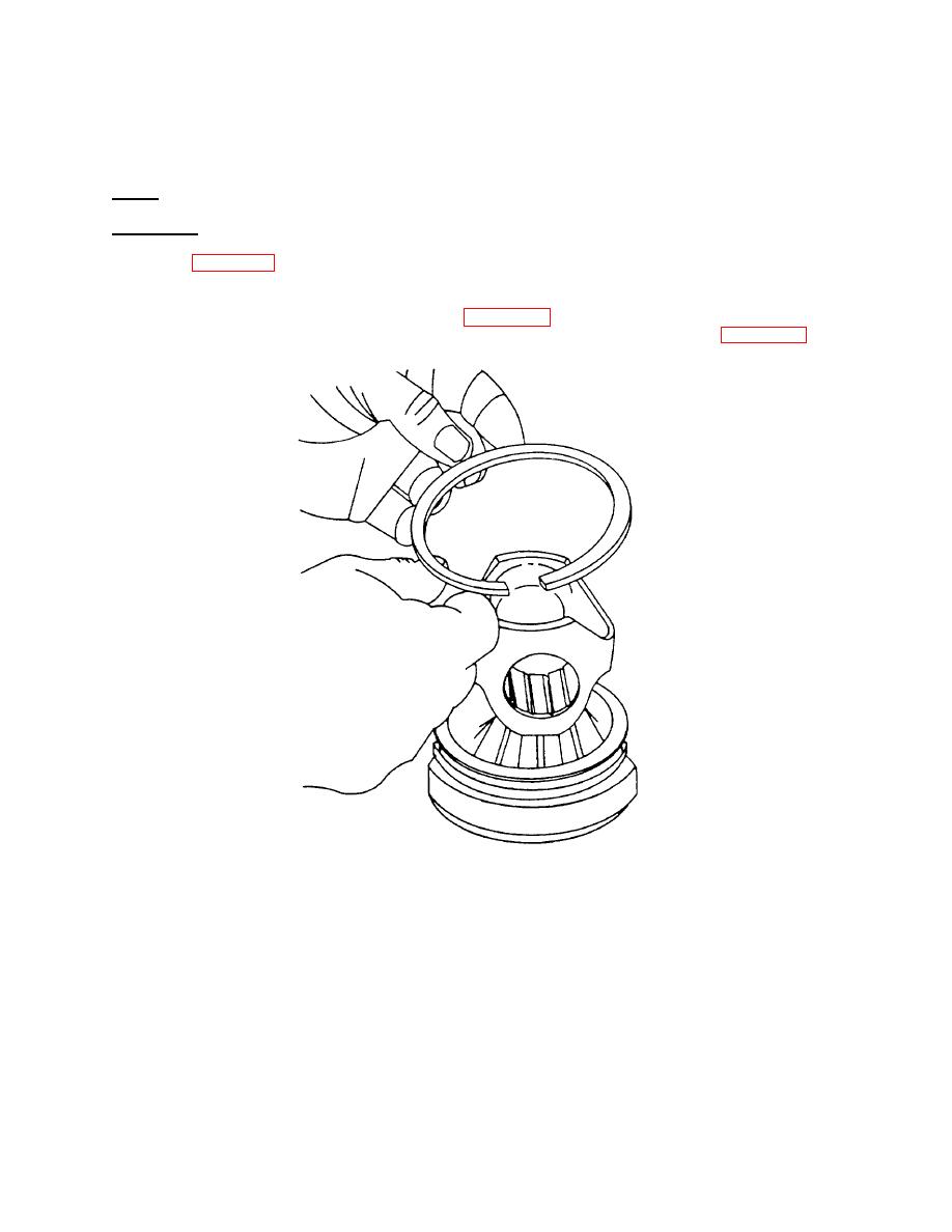
Figure 4-27. Installing Seal Ring |
|
||
| ||||||||||
|
|
 TM 55-1930-208-24
(6) Inspect connecting rod bearings for indications of scoring, overheating, or other damage. Replace a
damaged bearing.
(7) Inspect piston pin for signs of fretting. Replace a damaged piston pin.
e. Repair. Repair of the pistons and connecting rods is limited to the replacement of defective components.
f. Reassembly.
(1) Refer to figure 4-22 and install bearing (13) in piston skir (11). With new parts, there is .0005 to .0105 inch
t
clearance between the edge of the bushing and the groove in the piston crown.
(2) Lubricate seal ring (12) with engine oil (item 8, Appendix C). Install seal ring (12) on piston crown (10), with
the chamfer or counterbore directed toward bottom of the piston crown as shown in figure 4-27.
Figure 4-27 .
Installing Seal Ring .
NOTE
The current seal rings are made of cast iron and are identified by the tin-plating on the outside diameter, a
black oxide finish, or a dull cast iron color. These rings can be mixed in an engine. The former steel
ring, identified by a very shiny appearance, must not be used for service.
4-35
|
|
Privacy Statement - Press Release - Copyright Information. - Contact Us |
