 |
|||
|
|
|||
|
Page Title:
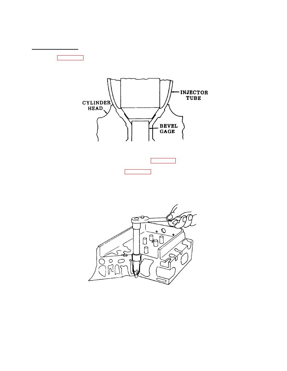
Figure 4-18. Bevel Gage Measurement. |
|
||
| ||||||||||
|
|
 TM 55-1930-208-24
4-10. HEAD, CYLINDER - Continued.
e. Assembly - Continued.
(14) Refer to figure 4-18 and install bevel gage into injector tube.
(15) Measure the gage to fire deck. The measurement should be flush to .014 inch.
Figure 4-18. Bevel Gage Measurement.
(16) If the injector tube requires further reaming, refer to figure 4-19.
(17) Place a few drops of cutting oil (item 6, Appendix C) on the bevel seat of the tube.
(18) Carefully lower the reamer until it contacts the bevel seat.
(19) Carefully ream and recheck the bevel cut until the measurement contained in steps (14) and (15) is reached.
Figure 4-19. Injector Tube, Finish Ream.
4-26
|
|
Privacy Statement - Press Release - Copyright Information. - Contact Us |
