 |
|||
|
|
|||
|
Page Title:
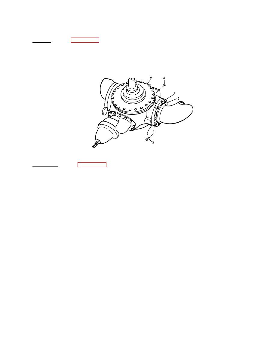
Figure 3-111. Transfer Pump, Removal / Installation. |
|
||
| ||||||||||
|
|
 TM 55-1930-208-24
3-54. PUMP, TRANSFER- Continued.
a. Removal. (Refer to figure 3-111).
(1) Remove sixteen screws (1) securing two flanges (2) and two gaskets (3) to pump casing.
(2) Attach a sling and lifting device, capable of lifting 250 lbs (113.50 Kg) to pump assembly. Apply tension to
lifting device and remove four nuts (4) and four screws (5). Remove pump (6) from mounting base.
Figure 3-111. Transfer Pump, Removal / Installation.
b. Disassembly. (Refer to figure 3-112).
(1) Remove one grease fitting (1) and one plug (2) from each bearing cover.
(2) Remove eight screws (3), bearing cover (4) and gasket (5).
(3) Bend the tabs of lockwasher (6) out of slot in locknut (7) and remove locknut with a hammer and punch.
Remove lockwasher (6) and bearing (8).
(4) Remove twelve screws (9) and hub (10). Remove grease fitting (11) and ring (12) from hub.
(5) Remove two head retaining screws (13) and screw them into the holes near the outer rim of head (14).
Insert an eye bolt in top of head and use a hoist for support. Remove remaining screws and tighten the
two in the tapped holes until the head separates from the casing. Remove the head, being careful not to
scrape or nick the shaft. Remove two screws (15) and two washers (16).
3-188
|
|
Privacy Statement - Press Release - Copyright Information. - Contact Us |
