 |
|||
|
|
|||
|
Page Title:
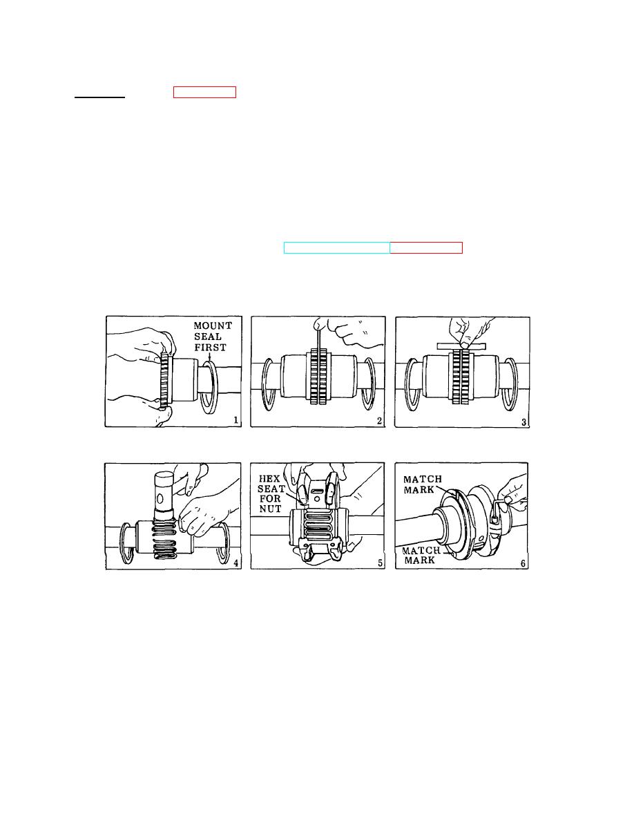
Figure 3-109. Coupling Assembly, Installation. |
|
||
| ||||||||||
|
|
 TM 55-1930-208-24
3-52. COUPLING ASSEMBLY - Continued.
b. Installation. (Refer to figure 3-109).
(1) Lightly coat seals with grease and place on shafts before mounting hubs (Step 1). Mount hubs on their
respective shafts so the hub face is flush with the end of its shaft.
(2) Using a 0.125 inch thick spacer bar, insert the base as shown in Step 2. Insert the bar to the same depth
at 90 intervals and measure the clearance between bar and hub face with feelers. The difference in
minimum and maximum measurements must not exceed 0.007 inch.
(3) Align so that a straight edges rests squarely on both hubs as shown in Step 3. Also check at 90intervals.
Check with feelers. The clearance must not exceed 0.008 inch. Tighten all foundation bolts and repeat
Steps 2 and 3. Realign coupling, if necessary.
(4) Pack gap and grooves with lubricant (TM 55-1930-208-10, paragraph 3-1) before inserting grid. When
grids are furnished in two or more segments, install them so that all cut ends extend in the same direction;
this will assure correct grid contact with non-rotating pin in cover halves. Spread the grid slightly to pass
over the coupling teeth and seat with a soft mallet as shown in Step 4.
Figure 3-109. Coupling Assembly, Installation.
3-182
|
|
Privacy Statement - Press Release - Copyright Information. - Contact Us |
