 |
|||
|
|
|||
|
Page Title:
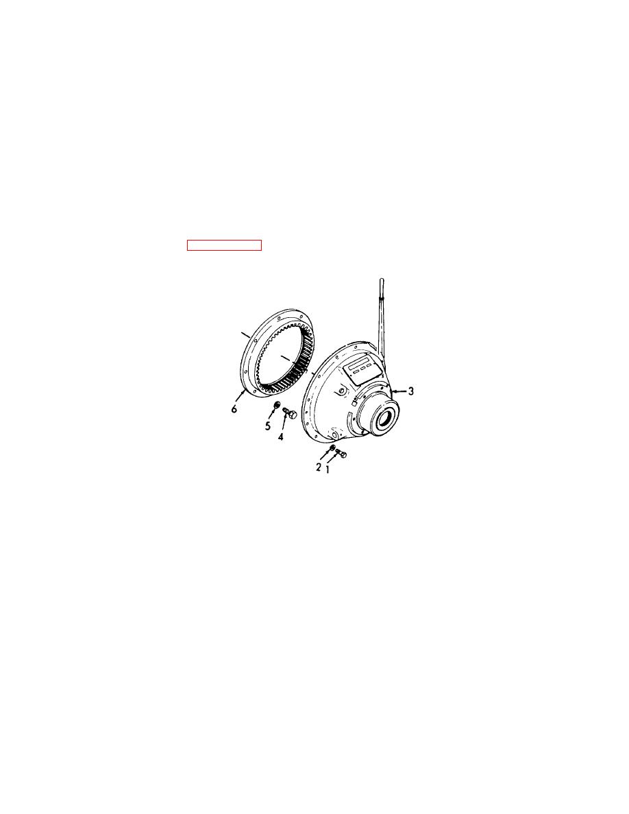
Figure 3-102. Clutch Replacement, Removal/Installation. |
|
||
| ||||||||||
|
|
 TM 55-1930-208-24
(2) Support power take-off assembly with a rope sling and chain hoist. Position power take-off assembly at the
rear of the flywheel housing with clutch drive shaft in line with pilot bearing in the flywheel.
(3) Push power take-off forward and guide forward end of drive shaft straight into the clutch pilot bearing and
engage the teeth on the outer diameter of clutch facings with the teeth in the inner diameter of clutch driving
ring.
(4) Install power take-off (3) on flywheel housing and secure with twelve bolts (1) and twelve lockwashers (2).
Tighten bolts to 46-50 lb-ft (62.8-68.3 Nm).
(5) Remove chain hoist and rope sling.
(6) Before applying a load and with clutch released, rotate drive shaft by hand to be sure it rotates freely.
(7) Adjust the clutch per paragraph 3-49.
Figure 3-102. Clutch Replacement, Removal/Installation.
3-171
|
|
Privacy Statement - Press Release - Copyright Information. - Contact Us |
